Starter boat assembly
The MARLIN Starter Kit builds one starter boat: a floating robot with two Underwater Thrusters for movement and a T Flipper for pushing Hex Links around. It will not win a Match on its own, but it gets your team on the water quickly and every part of it can be moved, replaced, or thrown away once you have your own ideas.
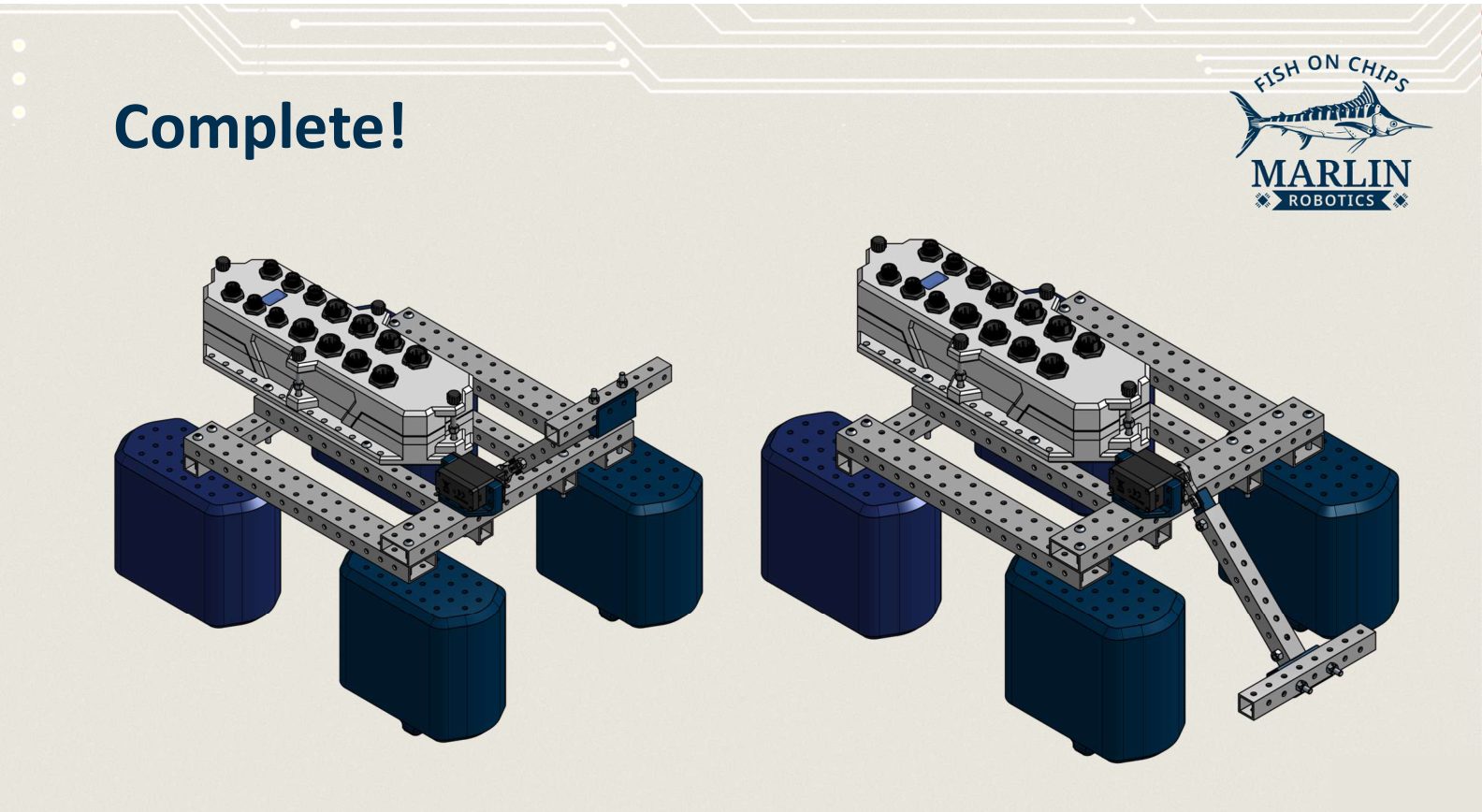
Build it in this order. Each stage finishes a piece that the next stage bolts together:
- Thruster floats — two of them
- T Flipper
- Robot Brain battery — fit it and close the box up
- Final assembly — the frame that joins everything
Tools
The kit includes one double ended spanner: 7 mm for M4 nuts, 5.5 mm for M3 nuts. You also need hex keys for the screw heads.
Wherever a step pairs a screw with a nut, hold the nut with the spanner while you turn the screw.
Know your parts
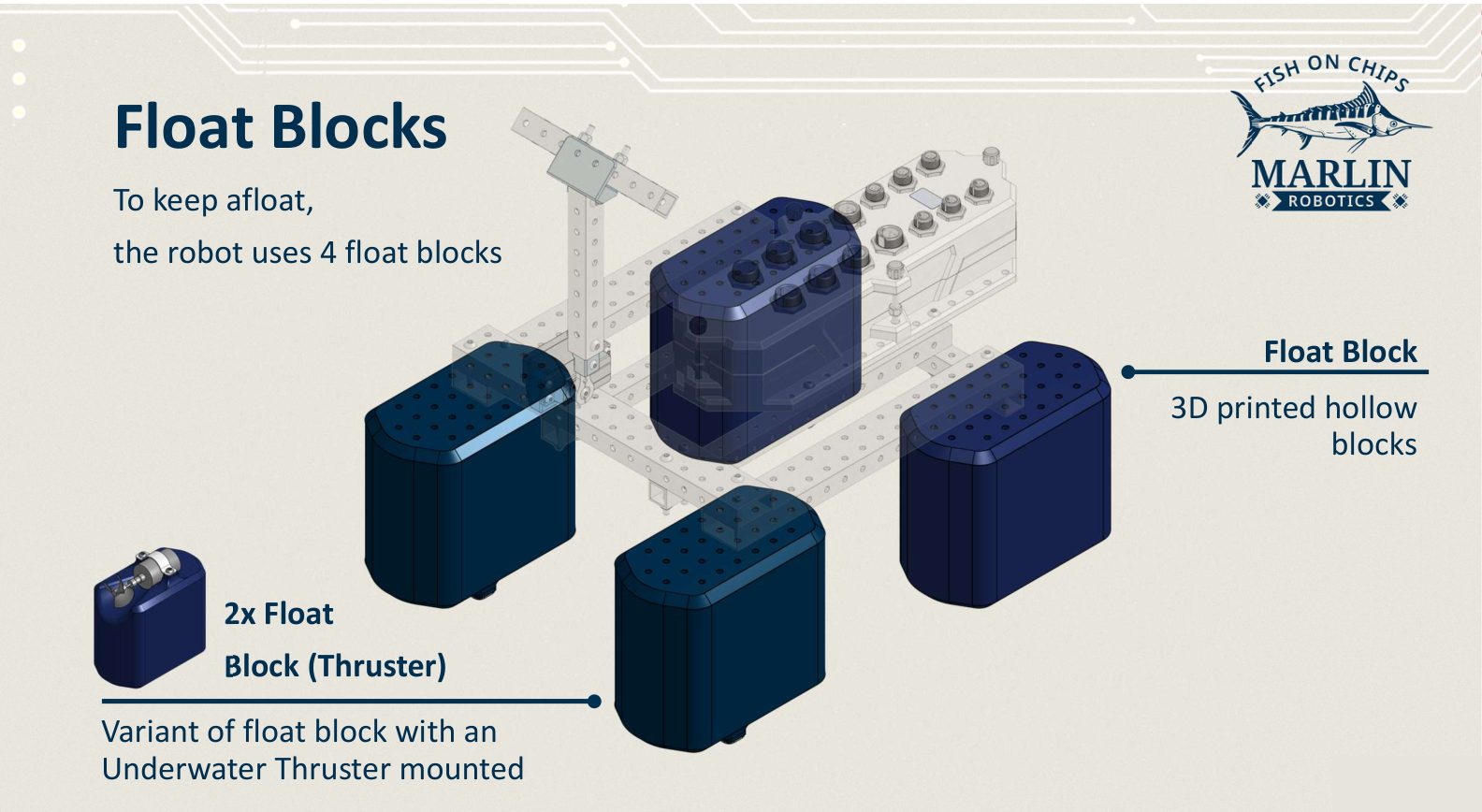
Float blocks
Four sealed 3D printed blocks keep the boat on the surface. Two are plain, and two are thruster blocks with a mounting recess for an Underwater Thruster.
Beams
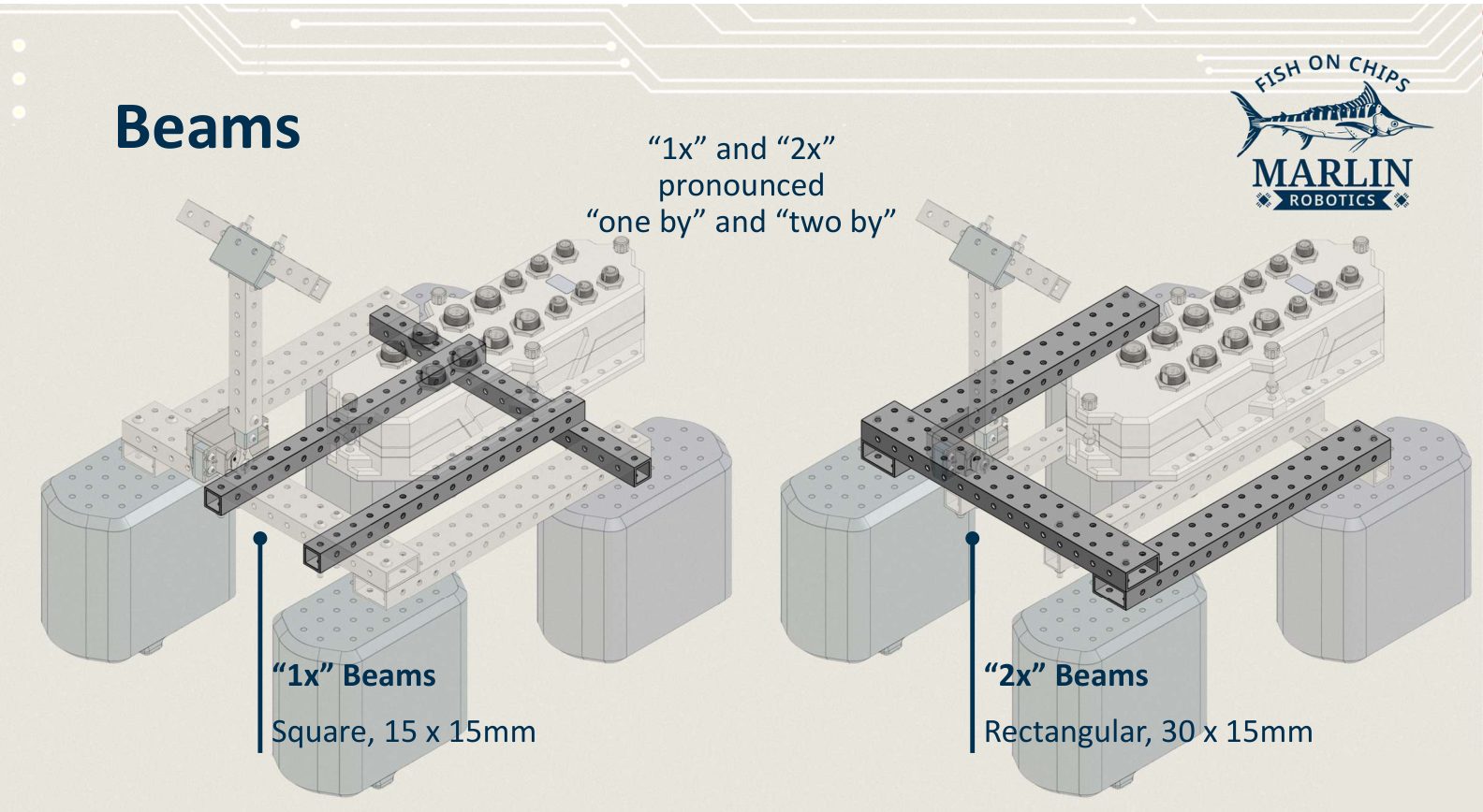
The frame is aluminium box tube drilled with 4 mm holes on a 15 mm pitch. Two profiles come in the kit, and the guide names them by profile:
| Name | Said as | Section |
|---|---|---|
| "1x" beam | "one by" | Square, 15 × 15 mm |
| "2x" beam | "two by" | Rectangular, 30 × 15 mm |
Robot Brain
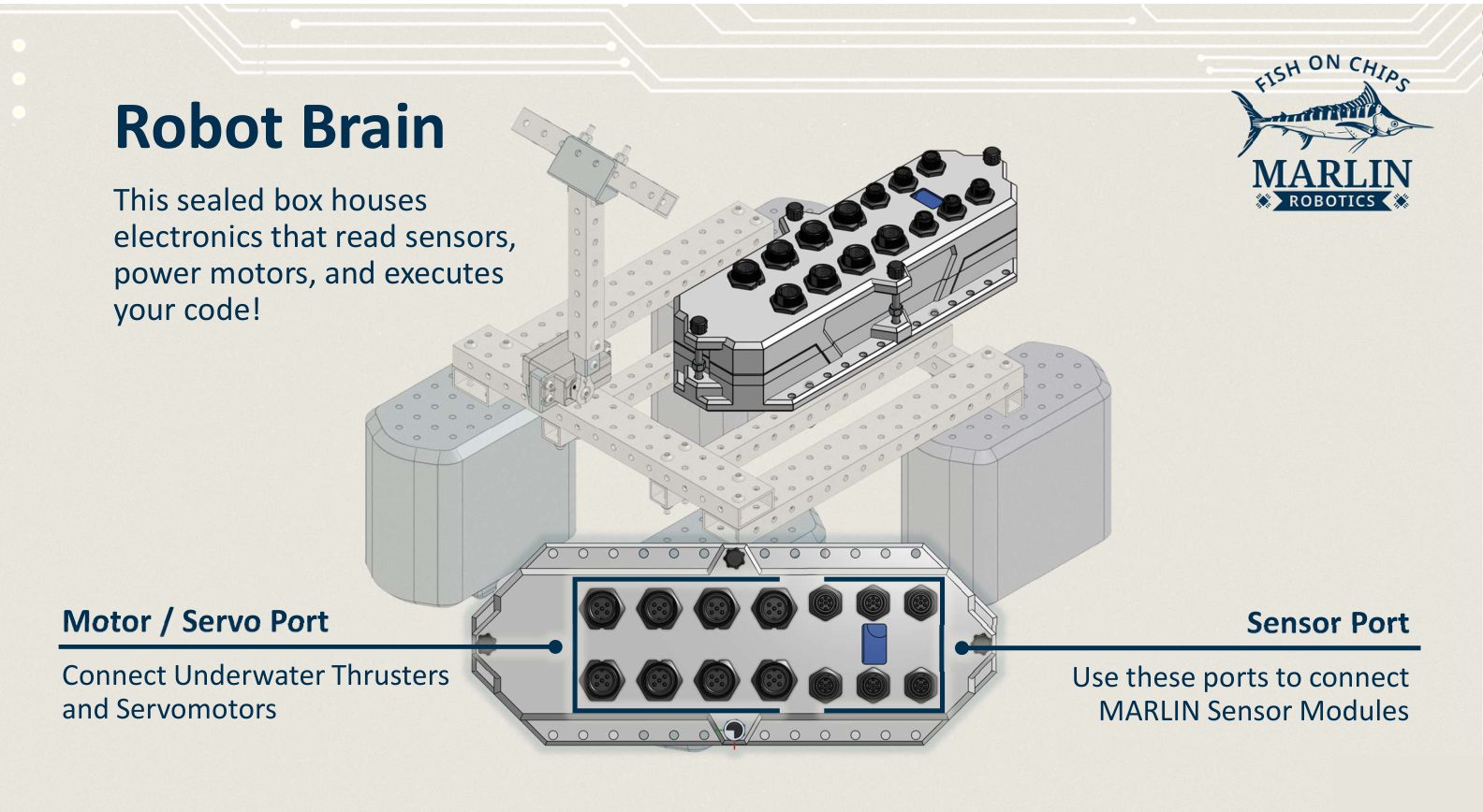
The sealed box that runs your code. Its ports are the ones you name in
Robot.configure(): Motor/Servo Ports M1 to
M8 for Thrusters and Servos, Sensor Ports S1 to S6 for MARLIN sensor
modules.
Thrusters and Servos
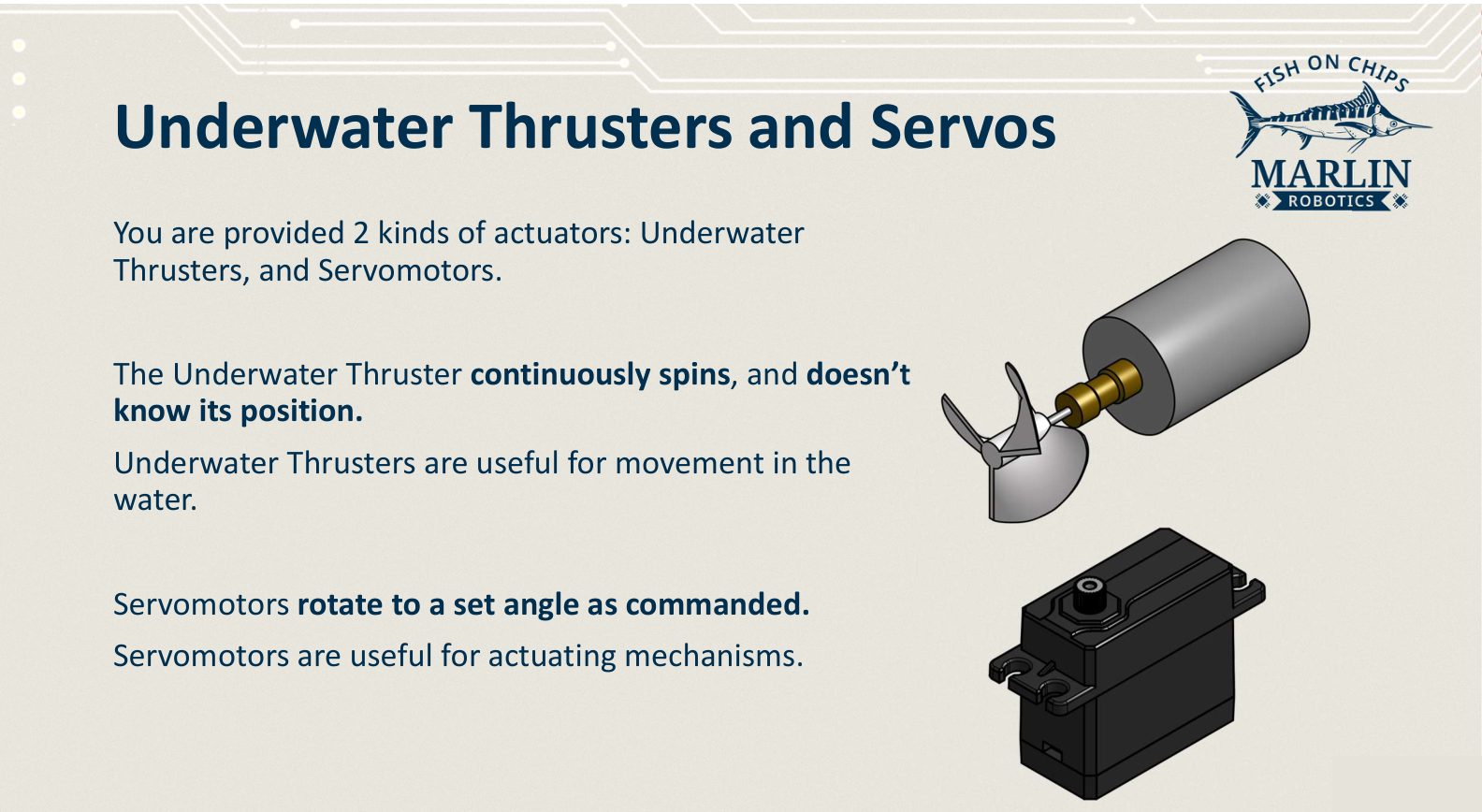
Two kinds of actuator, and the difference matters when you write code. An Underwater Thruster spins continuously and has no idea where it is. A Servomotor turns to the angle you command.
Screw codes
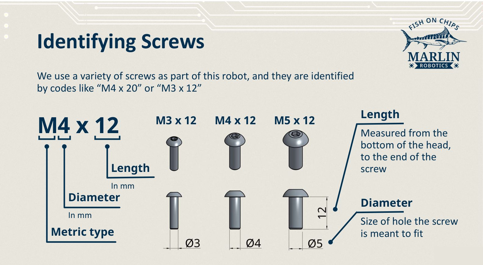
Screws are named M<diameter> x <length>, both in millimetres. Length is
measured from under the head, so an M4 × 20 and an M4 × 30 fit the same hole
but reach different depths.
Thruster floats
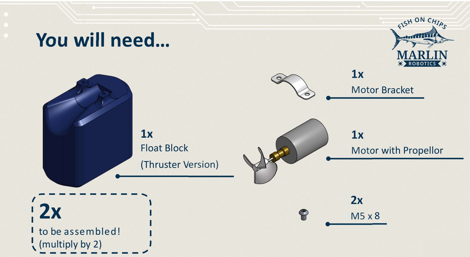
Build two of these. Per float:
| Part | Quantity |
|---|---|
| Float block, thruster version | 1 |
| Motor with propeller | 1 |
| Motor bracket | 1 |
| M5 × 8 screw | 2 |
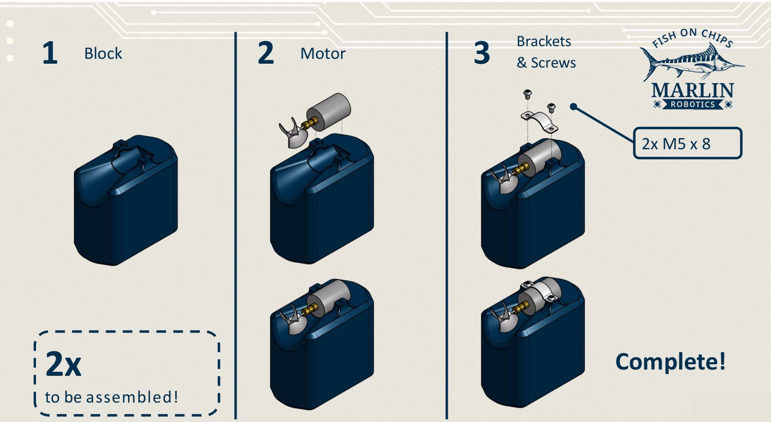
- Take a thruster float block.
- Lay the motor into the recess with the propeller facing out and the cable running into the block.
- Put the bracket over the motor body and fix it with 2× M5 × 8.
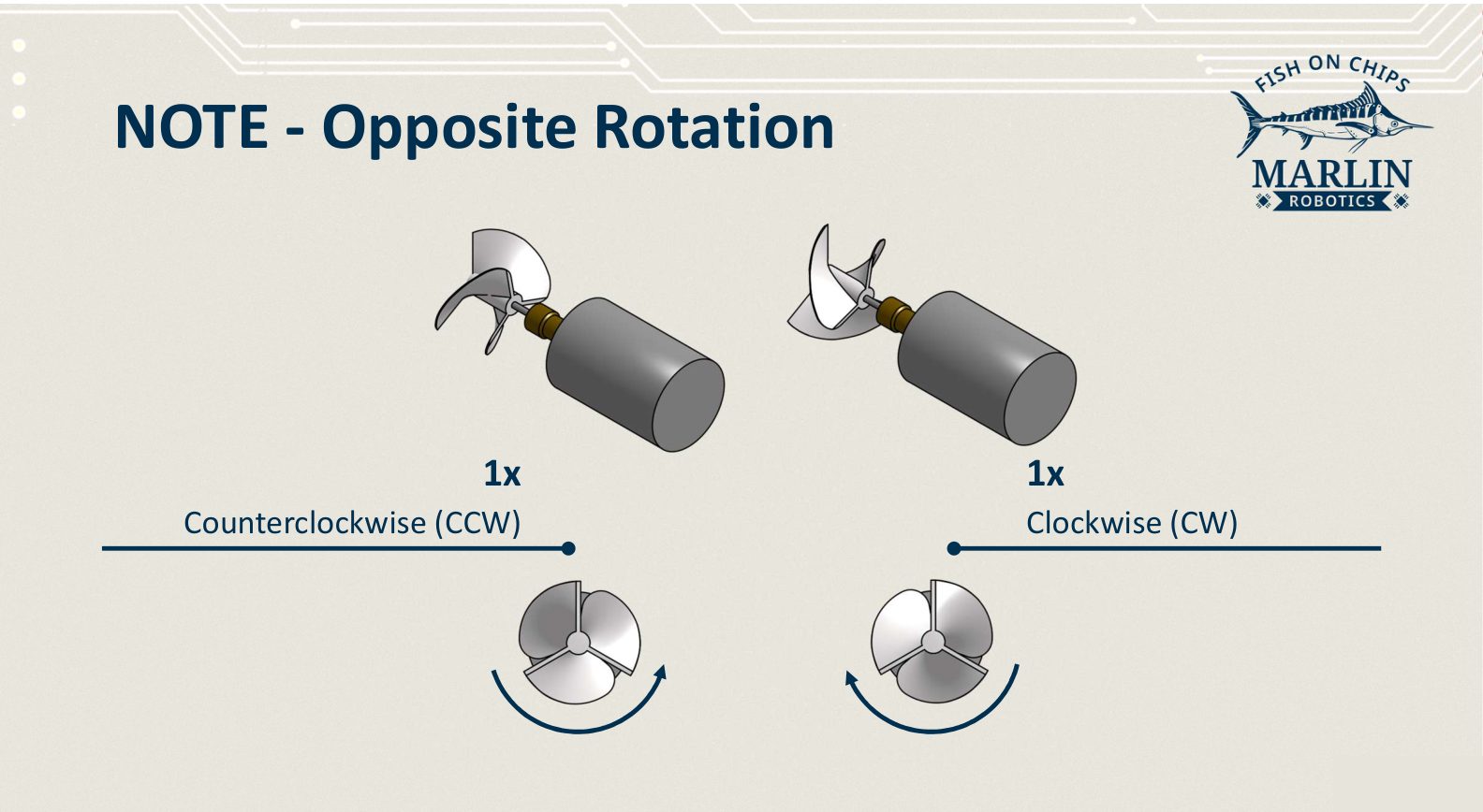
The two thrusters are not identical
One motor has a clockwise propeller and the other counterclockwise. Fit one of each, one per float. Two of the same rotation will make the boat yaw whenever you drive straight.
T Flipper
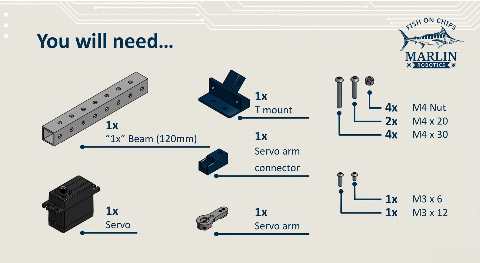
The T Flipper is the starter boat's arm. A servo tilts a crossbar up and down to break up scored Hex Links, flip them to your Alliance colour, or push them around.
| Part | Quantity |
|---|---|
| "1x" beam, 120 mm (crossbar) | 1 |
| "1x" beam, 120 mm (upright) | 1 |
| T mount | 1 |
| Servo arm connector | 1 |
| Servo arm | 1 |
| Servo | 1 |
| M4 × 30 screw | 4 |
| M4 × 20 screw | 2 |
| M4 nut | 4 |
| M3 × 12 screw | 1 |
| M3 × 6 screw | 1 |
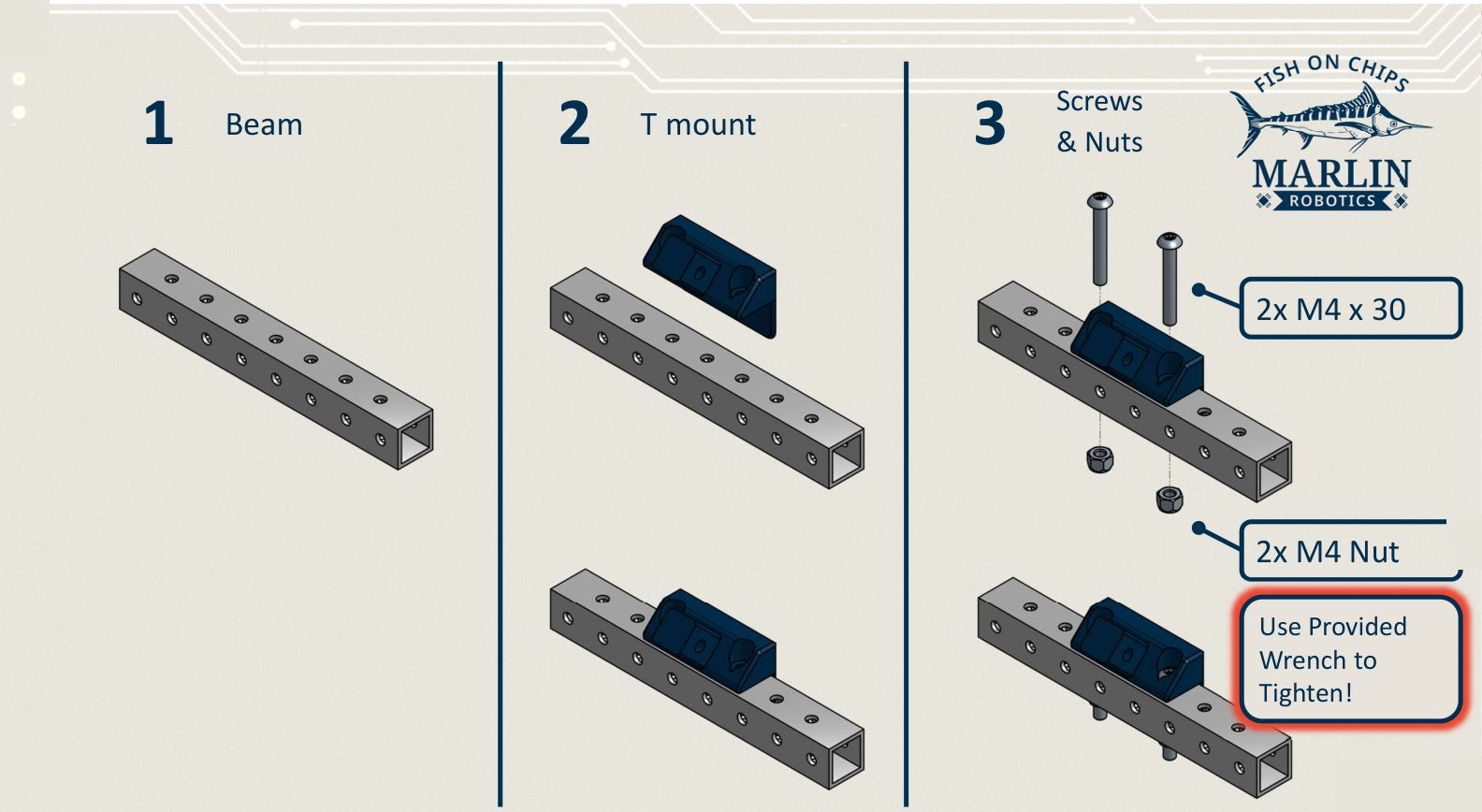
Crossbar and mount
- Lay the 120 mm "1x" beam flat.
- Sit the T mount across it, over the centre holes.
- Fix it with 2× M4 × 30 and 2× M4 nuts.
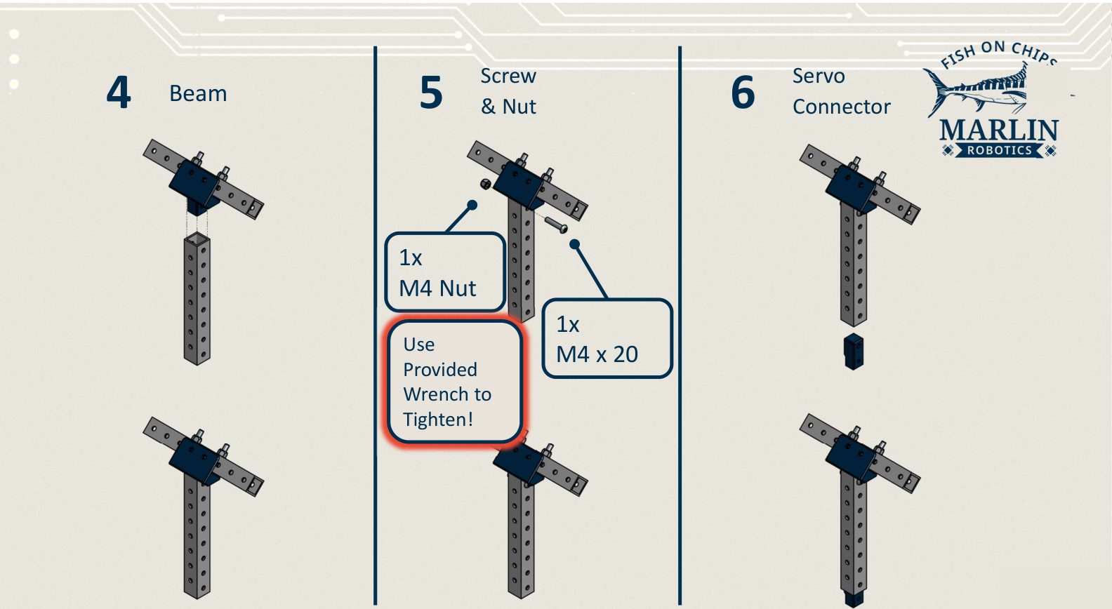
Upright and servo connector
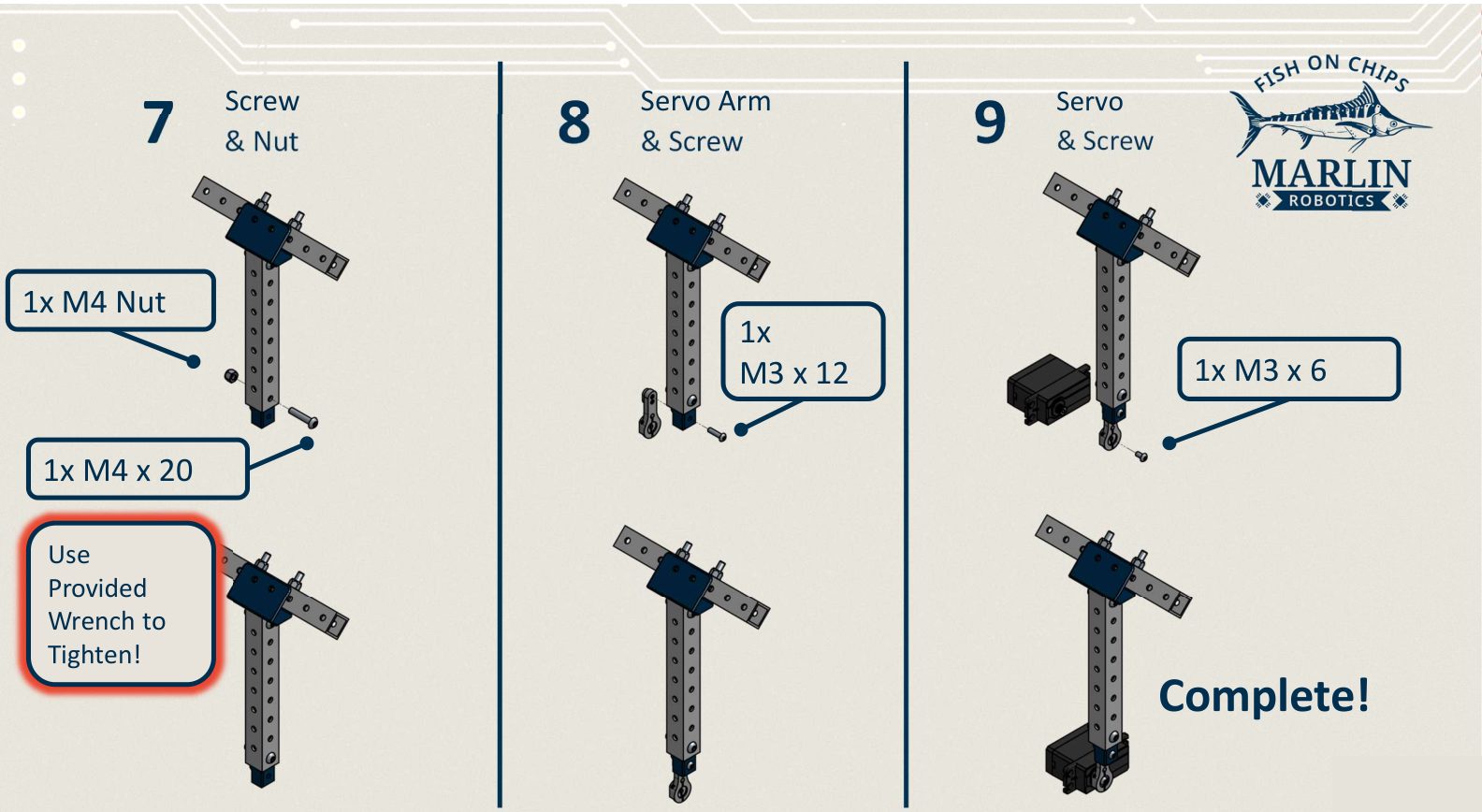
- Stand the second 120 mm "1x" beam upright and slide its end into the T mount.
- Fix it with 1× M4 × 20 and 1× M4 nut.
- Push the servo arm connector onto the bottom end of the upright.
Servo arm and servo
- Fix the servo arm connector with 1× M4 × 20 and 1× M4 nut.
- Attach the servo arm to the connector with 1× M3 × 12.
- Attach the servo to the arm with 1× M3 × 6.
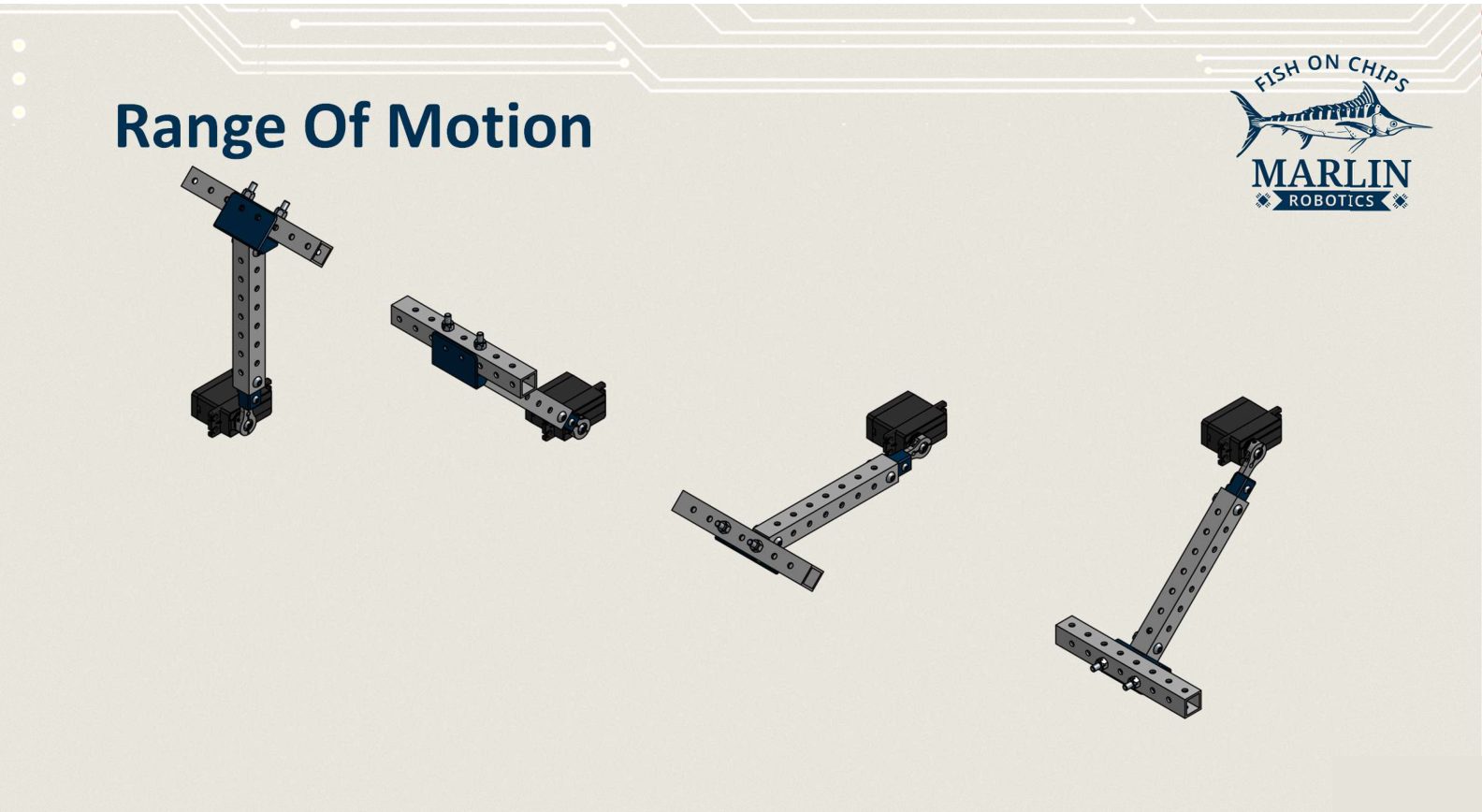
Before you bolt it to the boat, turn the servo by hand through its travel. The crossbar should sweep from pointing up, through horizontal, to pointing down, without fouling the upright.
Robot Brain battery
The Robot Brain ships sealed. Open it once to fit the battery, then close it properly. Everything inside is electronics, and the seal is the only thing keeping the water out.
Open it upright, never upside down
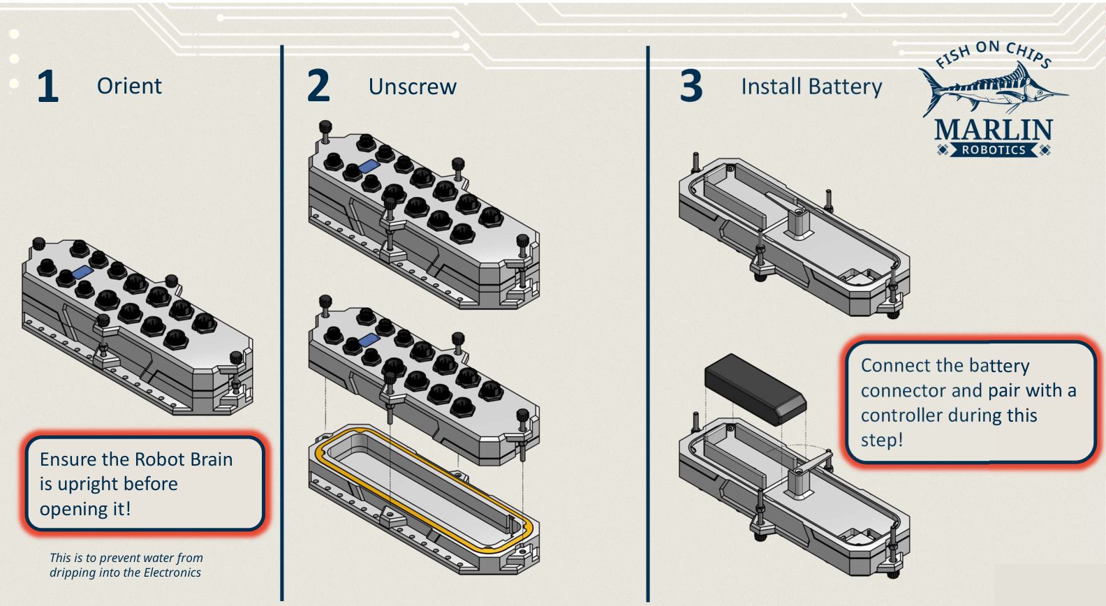
Hold the Robot Brain the right way up before you loosen anything. Water sitting on the lid will run straight into the electronics if you open it inverted.
- Set the Robot Brain upright on the bench.
- Loosen the lid screws and lift the top off the baseplate.
- Drop the battery into the tray and connect the battery connector. The Brain powers up, so pair it with a controller now while the box is open.
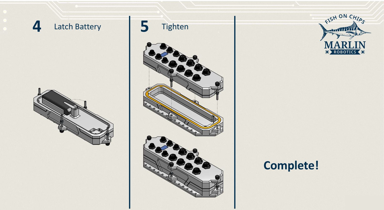
- Latch the battery down so it cannot slide around.
- Refit the top and tighten the screws evenly.
Check the gasket before you tighten
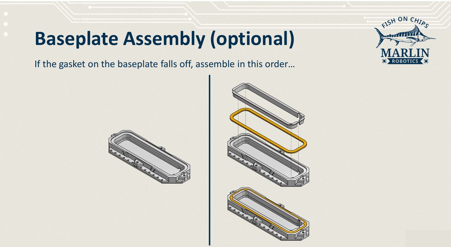
The gasket must sit in its groove all the way round. If it has fallen out, lay it back into the baseplate groove, then fit the retaining ring over it before closing the lid.
Final assembly
Everything below assumes you have 2 thruster floats, 1 T Flipper, and 1 closed Robot Brain ready.
| Part | Quantity |
|---|---|
| "1x" beam, 240 mm | 3 |
| "2x" beam, 240 mm | 3 |
| Float block, plain | 2 |
| Flipper servo mount | 1 |
| M4 × 50 screw | 2 |
| M4 × 40 screw | 4 |
| M4 × 35 screw | 8 |
| M4 × 30 screw | 2 |
| M4 nut | 8 |
| M3 × 12 screw | 4 |
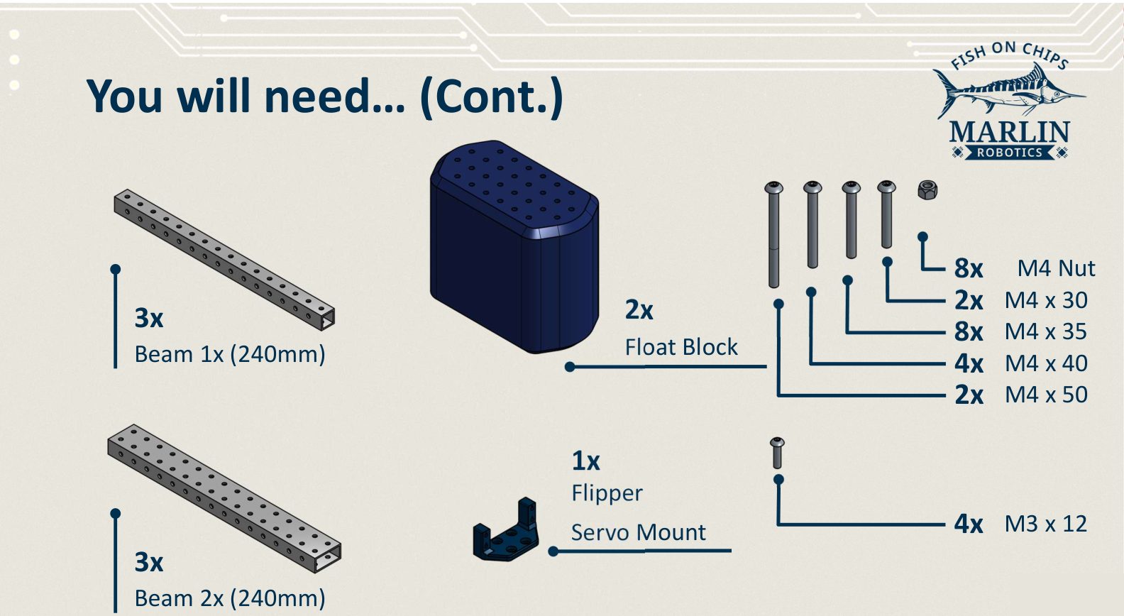
Two of the 240 mm "1x" beams are used here: the back beam and the centre beam.
1. Back beam
Set a 240 mm "1x" beam aside as the back beam. It carries the rear end of the Robot Brain in the next step.
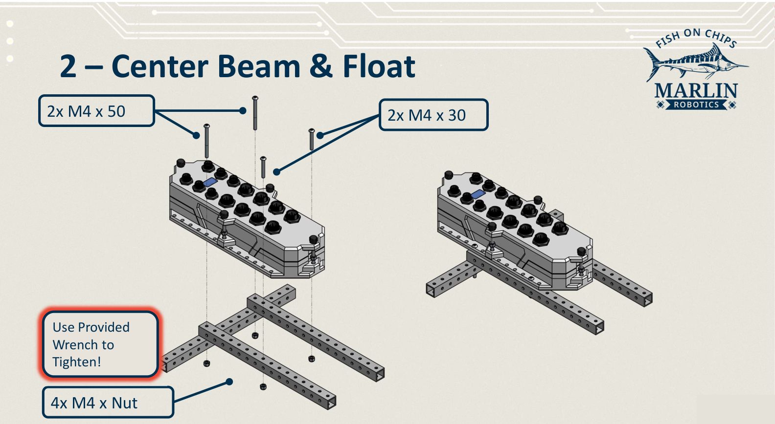
2. Centre beam and Robot Brain
- Lay the centre beam along the boat and the back beam across it.
- Sit the Robot Brain on top, mounting feet over the beam holes.
- Fix it with 2× M4 × 50 and 2× M4 × 30, and 4× M4 nuts underneath.
3. Front beam
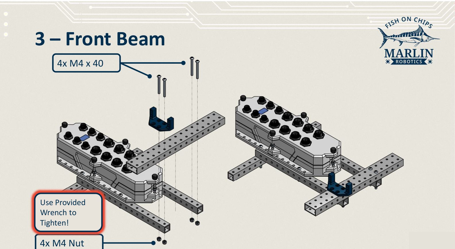
- Lay a 240 mm "2x" beam across the front of the frame.
- Place the flipper servo mount on it, facing forward.
- Fix both with 4× M4 × 40 and 4× M4 nuts.
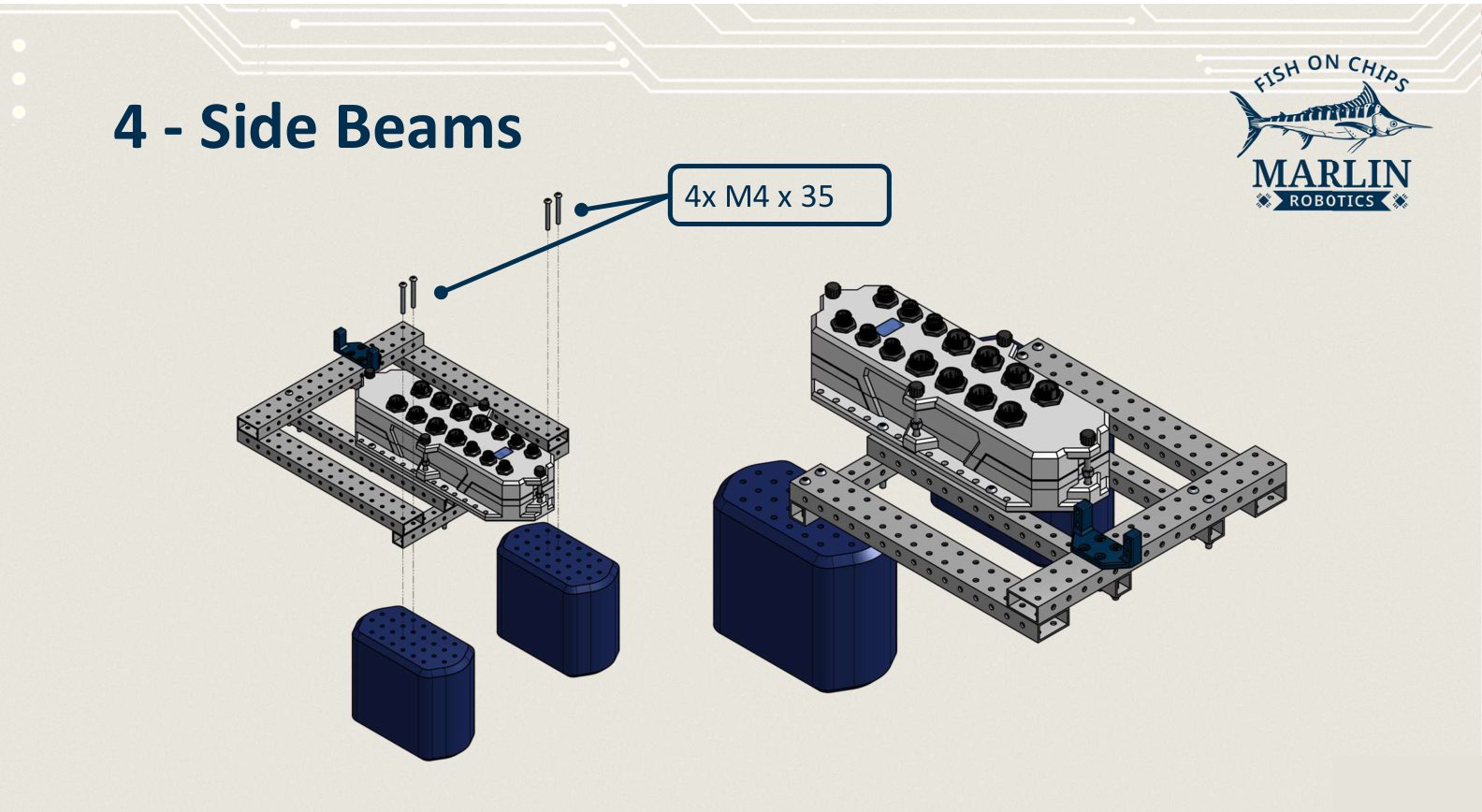
4. Side beams and plain floats
- Lay the two remaining 240 mm "2x" beams along the sides, bridging the front and back beams.
- Bring the two plain float blocks up under the outer ends.
- Fix each float with 2× M4 × 35 down through the side beam, 4× in total.
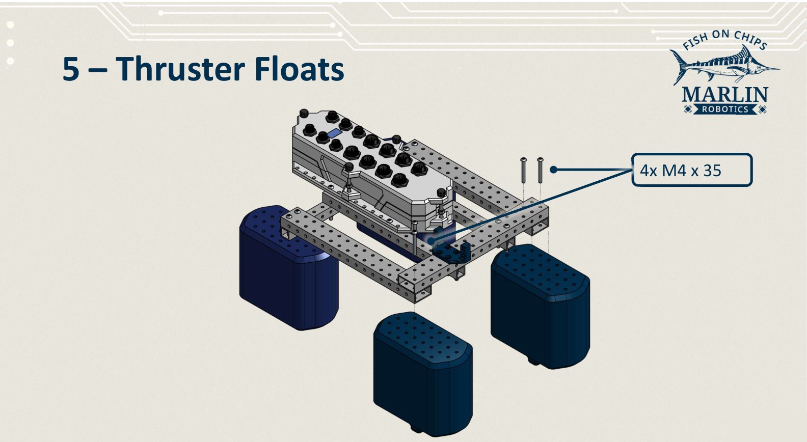
5. Thruster floats
Fit the two thruster floats to the remaining positions with 4× M4 × 35, two per float. Point both propellers the same way, and keep the clockwise and counterclockwise floats on opposite sides.
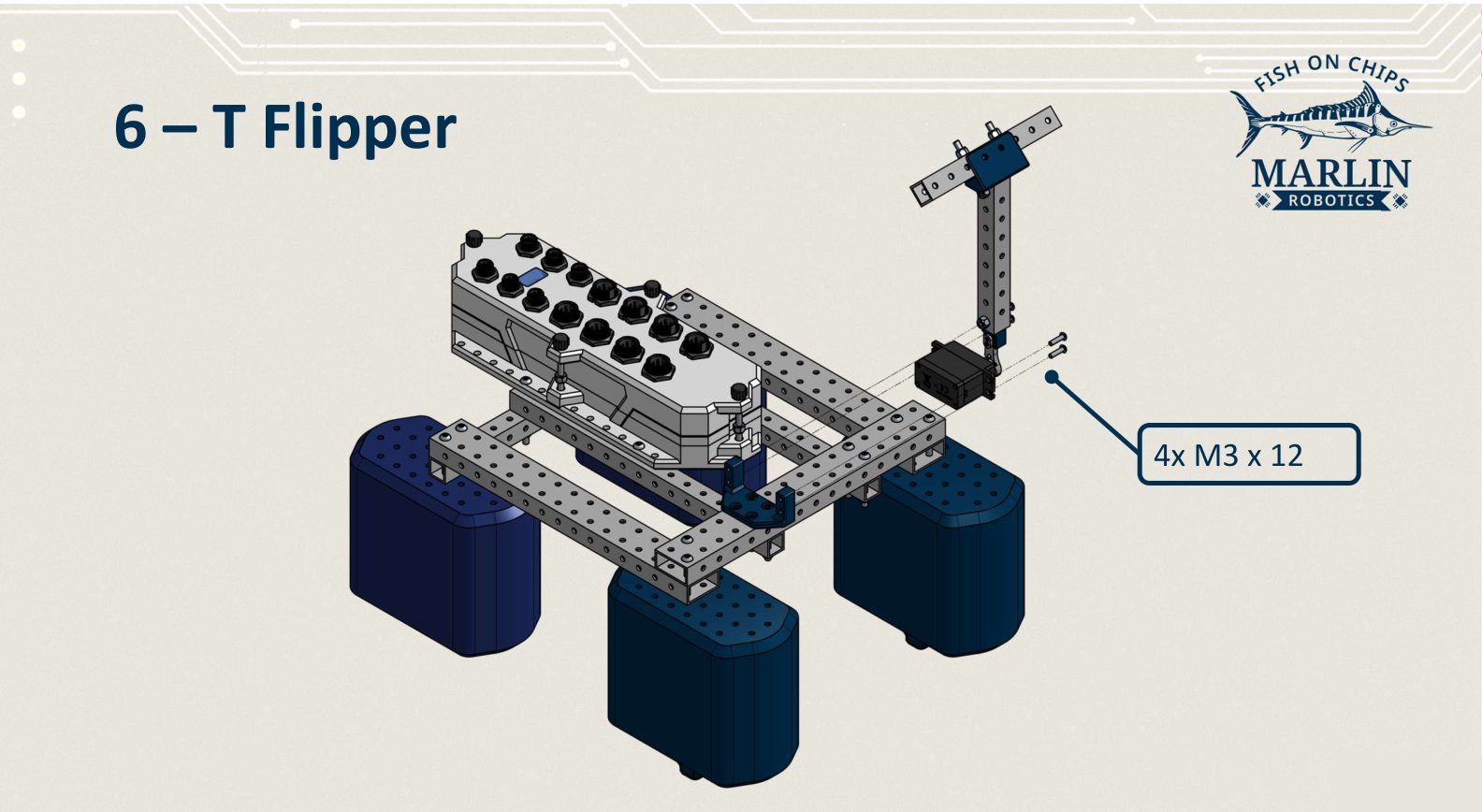
6. T Flipper
Bolt the T Flipper's servo to the flipper servo mount on the front beam with 4× M3 × 12.
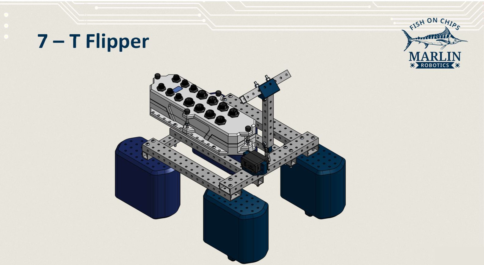
With the flipper mounted, tilt it by hand through its full travel once more. The crossbar must clear the front beam and the floats at both ends.
Next steps
Plug the thrusters and the flipper servo into the Motor/Servo Ports, note which port each one uses, then declare them in code:
The port names have to match what you physically plugged in. See Hardware configuration for the rules, and Your first program to make the boat move.