Kit Build
You have met every part in the box. This page assembles them into the starter Robot: a floating frame on four Hulls, driven by two Underwater Thrusters, with a T Flipper on the front for pushing Hex Links around. It will not win a Match on its own, but it gets your team on the water quickly, and every part of it can be moved, replaced, or thrown away once you have your own ideas.
If a part name below is unfamiliar, look it up in Kit Intro.
Build it in this order. Each stage finishes a sub-assembly that a later stage bolts onto the frame:
- Thruster Hulls — two of them
- T Flipper
- Main assembly — the frame that joins everything
- Sensors and cables
- Robot Brain battery
Before you start
The kit includes one double-ended Combination Wrench: 7 mm for M4 nuts, 5.5 mm for M3 nuts. Use the Allen Key Set for the screw heads, and pick the size that fits properly — a loose key will round out the socket.
Wherever a step pairs a screw with a nylock nut, hold the nut with the wrench and turn the screw. Nylock nuts have a nylon insert that grips the thread, so they feel stiff for the last few turns. That is normal, and it is what stops the Robot shaking itself apart in the water.
Screws are named M<thread diameter> x <length>, both in millimetres, with the
length measured from under the head. An M4 × 20 and an M4 × 30 drop into the
same hole but reach very different depths, so check the number on the bag
before you reach for one.
Beams have an odd side and an even side
Look down the face of a beam: one face has an odd number of holes in its row, the other has an even number. Several steps below depend on which face is up, and getting it wrong shifts everything by half a hole. The diagrams call this out where it matters.
1. Thruster Hulls
Build two of these. They are identical except for the direction their propellers turn.
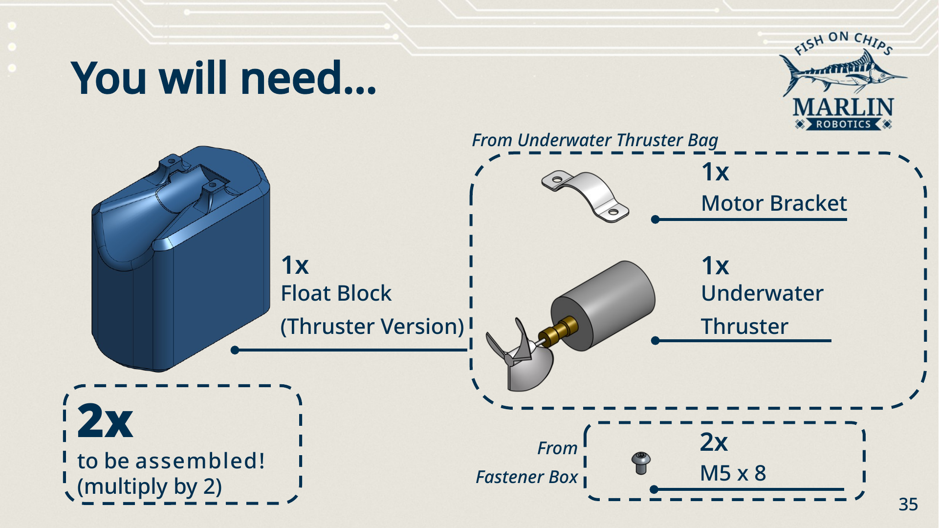
Parts (per hull)
| Part | Quantity | From |
|---|---|---|
| Thruster Hull (Float Block, thruster version) | 1 | — |
| Underwater Thruster | 1 | Underwater Thruster Bag |
| Motor Bracket | 1 | Underwater Thruster Bag |
| M5 × 8 screw | 2 | Fastener Box |
The two Thrusters are not identical
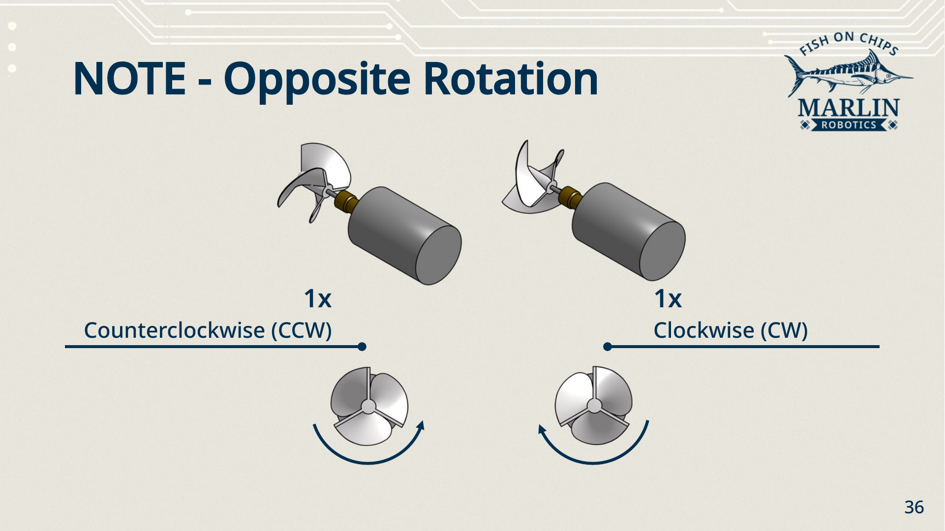
One Thruster has a Clockwise (CW) propeller and the other a Counterclockwise (CCW) propeller. Fit one of each — one per hull. Two of the same rotation will make the Robot yaw every time you try to drive straight.
Steps
- Take a Thruster Hull and set it the right way up, recess on top.
- Lay the Thruster into the recess with the propeller facing out. Push it back so it sits flush against the back of the mount — if it creeps forward, the bracket will not clamp it squarely.
- Put the Motor Bracket over the Thruster body and fix it with 2× M5 × 8.
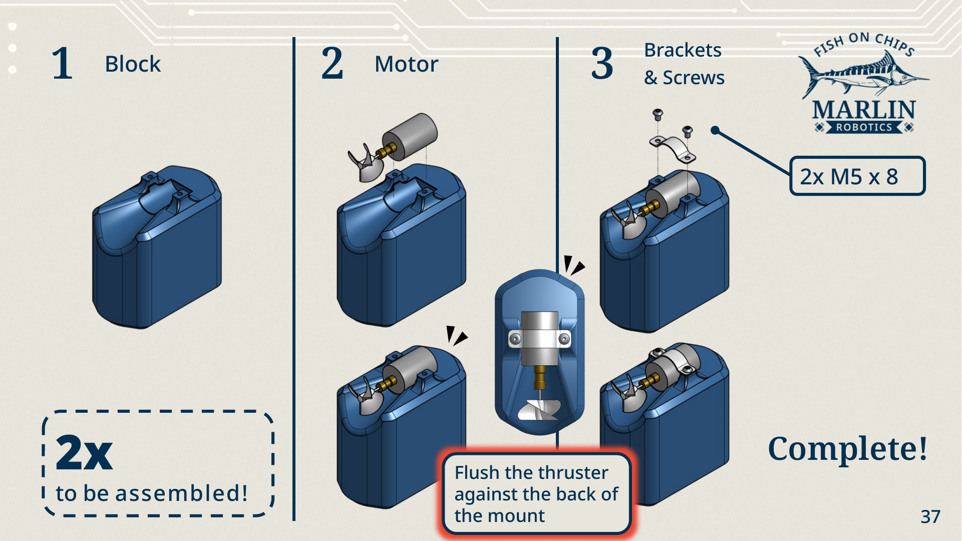
You should have: two finished Thruster Hulls, one CW and one CCW. Keep track of which is which — it matters in step 3.
2. T Flipper
The T Flipper is the starter Robot's arm. A Servo tilts a crossbar up and down to break up scored Hex Links, flip them to your Alliance colour, or shove them around.
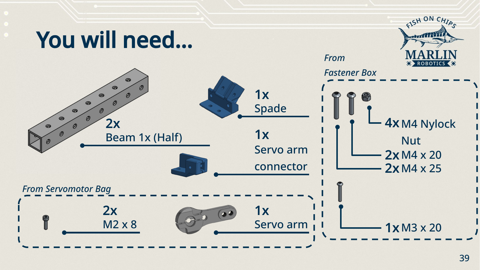
Parts
| Part | Quantity | From |
|---|---|---|
| Beam 1x (half) | 2 | — |
| Spade Piece | 1 | — |
| Servo Arm Connector | 1 | — |
| Servo Arm | 1 | Servomotor Bag |
| M2 × 8 screw | 2 | Servomotor Bag |
| M4 × 25 screw | 2 | Fastener Box |
| M4 × 20 screw | 2 | Fastener Box |
| M4 nylock nut | 4 | Fastener Box |
| M3 × 20 screw | 1 | Fastener Box |
Optional screws need extra fasteners
Steps 6, 9 and 13 add a second screw to a joint that is already held. They are optional, but the arm is much stiffer with them in. Each one needs a fastener beyond the list above — grab them from the Fastener Box as you go.
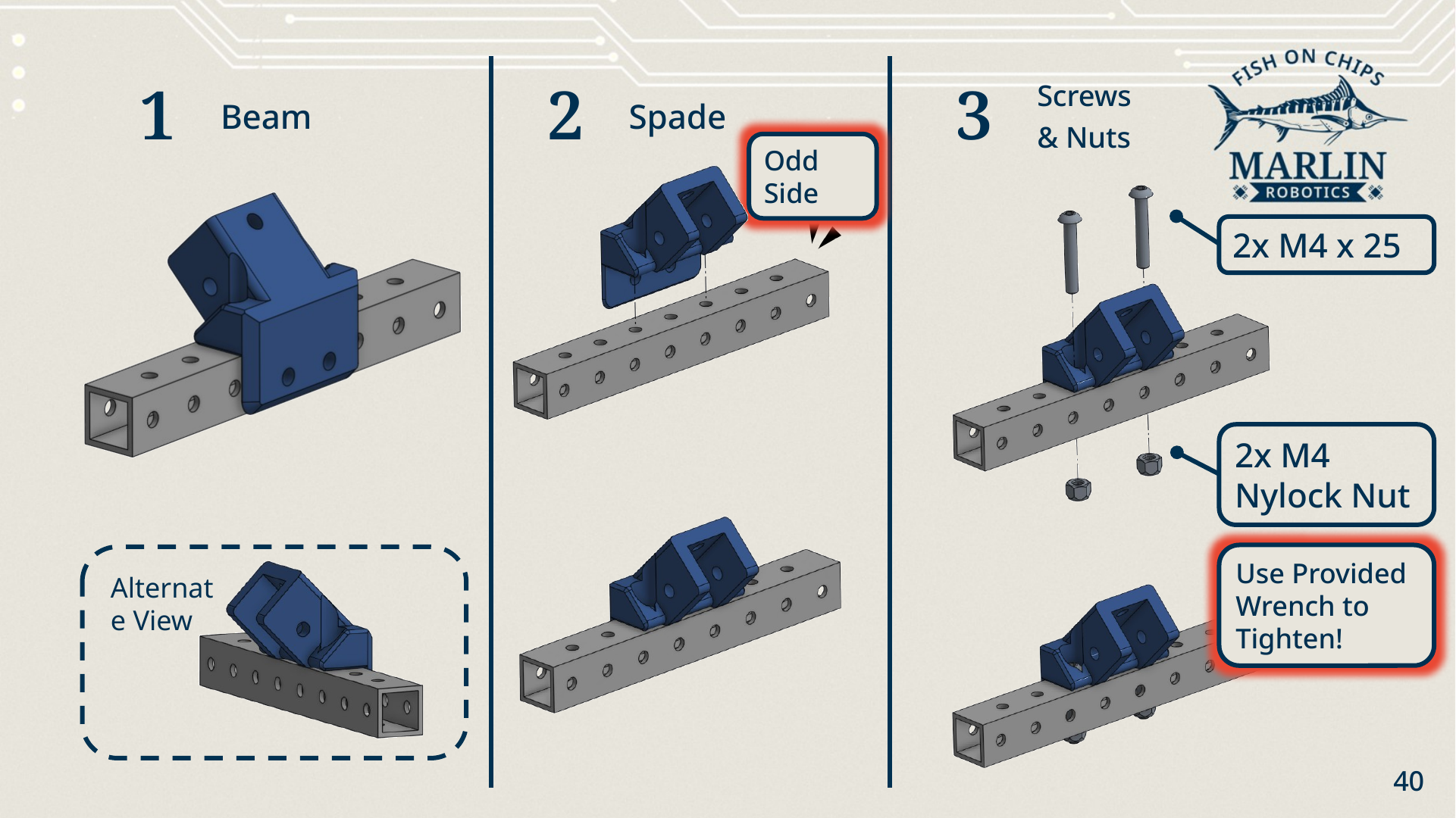
Crossbar and spade
- Beam. Lay one half-length 1x beam flat.
- Spade. Sit the Spade Piece across the middle of it, on the beam's odd side.
- Screws and nuts. Fix it with 2× M4 × 25 and 2× M4 nylock nuts. Tighten with the provided wrench.
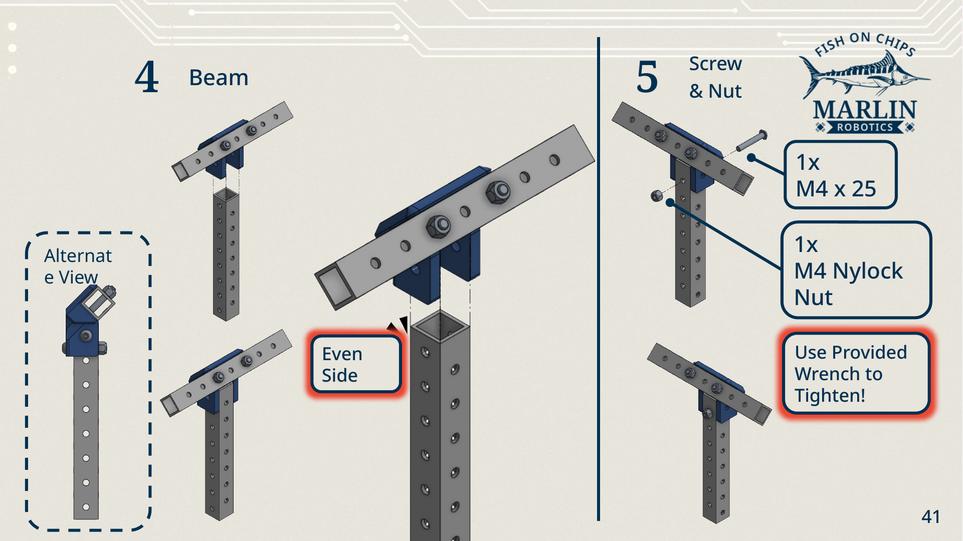
Upright
- Beam. Stand the second half-length 1x beam upright and slide its end into the Spade Piece, even side facing out.
- Screw and nut. Fix it with 1× M4 × 25 and 1× M4 nylock nut.
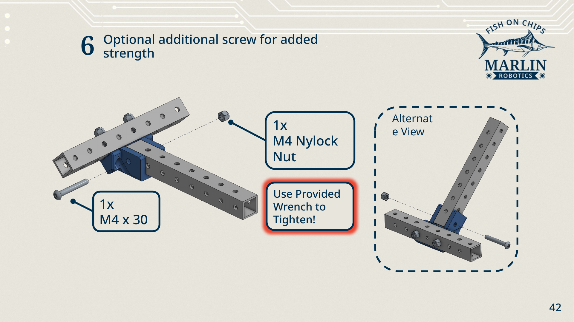
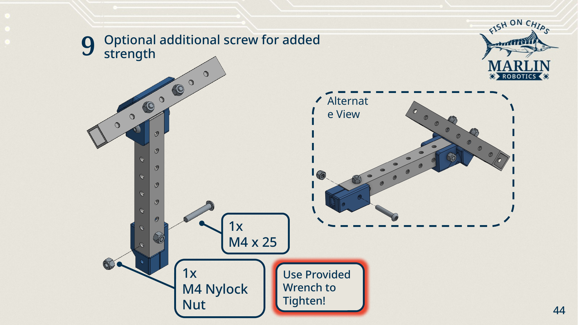
- Optional. Add 1× M4 × 30 and 1× M4 nylock nut through the second hole of the same joint for extra strength.
Servo Arm Connector
- Servo Arm Connector. Push the connector onto the bottom end of the upright beam, over the beam's even side.
- Screw and nut. Fix it with 1× M4 × 20 and 1× M4 nylock nut.
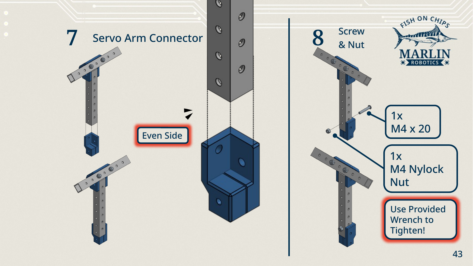
- Optional. Add 1× M4 × 25 and 1× M4 nylock nut through the connector's second hole.
Servo Arm
-
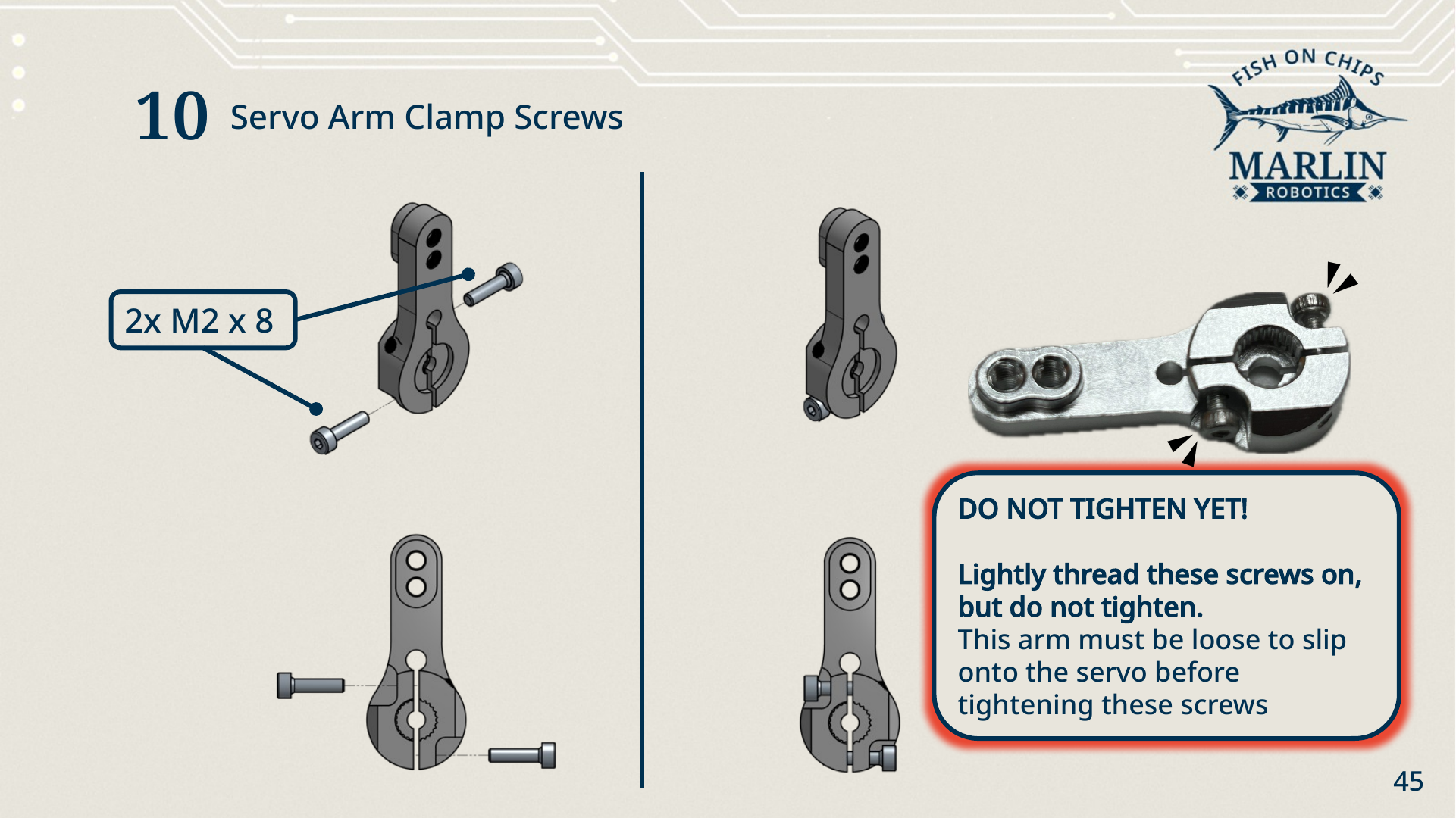
Clamp screws. Thread the 2× M2 × 8 into the Servo Arm's clamp.
Do not tighten the clamp screws yet
Thread them on lightly and stop. The clamp has to stay loose enough to slip over the Servo's splined output shaft later. Tighten it now and you will be undoing it in a few minutes.
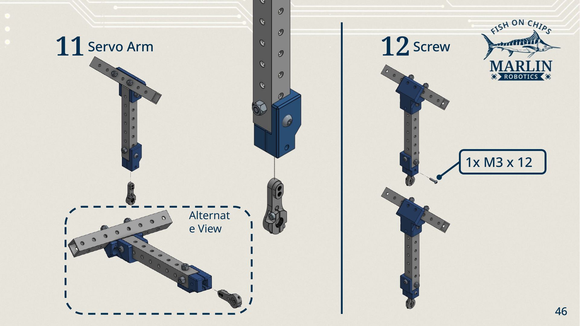
- Servo Arm. Offer the Servo Arm up to the bottom of the Servo Arm Connector.
- Screw. Fix it with 1× M3 × 12.
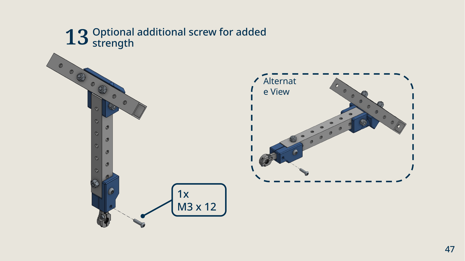
- Optional. Add 1× M3 × 12 through the connector's second hole.
The T Flipper does not go onto the Servo yet
The Servo has to be zeroed in code before the arm goes on, so that the crossbar's sweep lines up with the Servo's travel. You will do that in Your First Program. Until then, set the finished T Flipper aside with its clamp screws still loose.
3. Main assembly
This is where the sub-assemblies become a Robot.
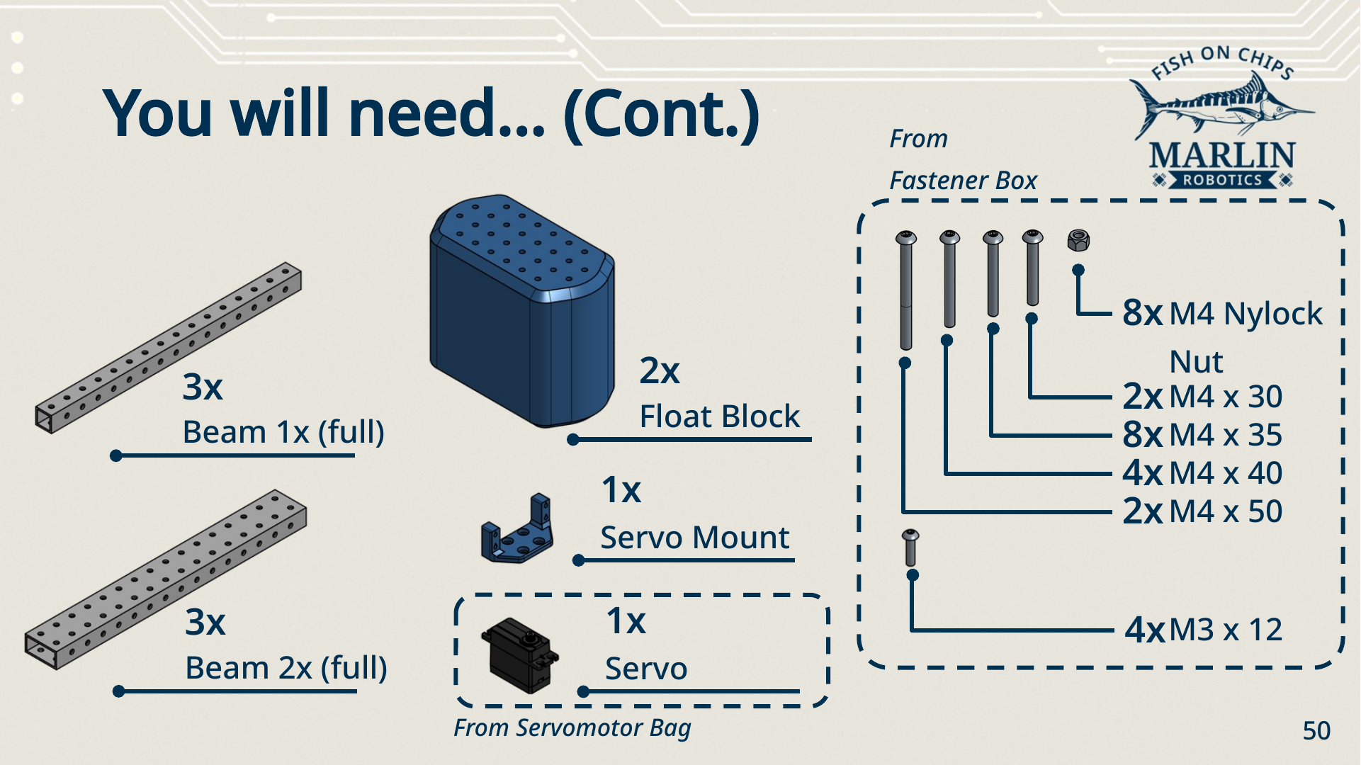
Parts
| Part | Quantity | From |
|---|---|---|
| Robot Brain | 1 | provided assembled |
| Thruster Hull | 2 | assembled in step 1 |
| Hull (plain Float Block) | 2 | — |
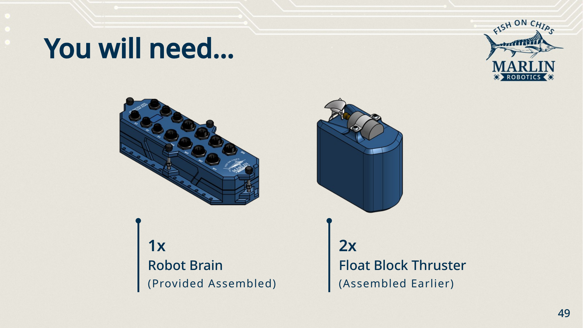
| Beam 1x (full) | 3 | — |
| Beam 2x (full) | 3 | — |
| Servomotor Mount | 1 | — |
| Servo | 1 | Servomotor Bag |
| M4 × 50 screw | 2 | Fastener Box |
| M4 × 40 screw | 4 | Fastener Box |
| M4 × 35 screw | 8 | Fastener Box |
| M4 × 30 screw | 2 | Fastener Box |
| M4 nylock nut | 8 | Fastener Box |
| M3 × 12 screw | 4 | Fastener Box |
Front beam
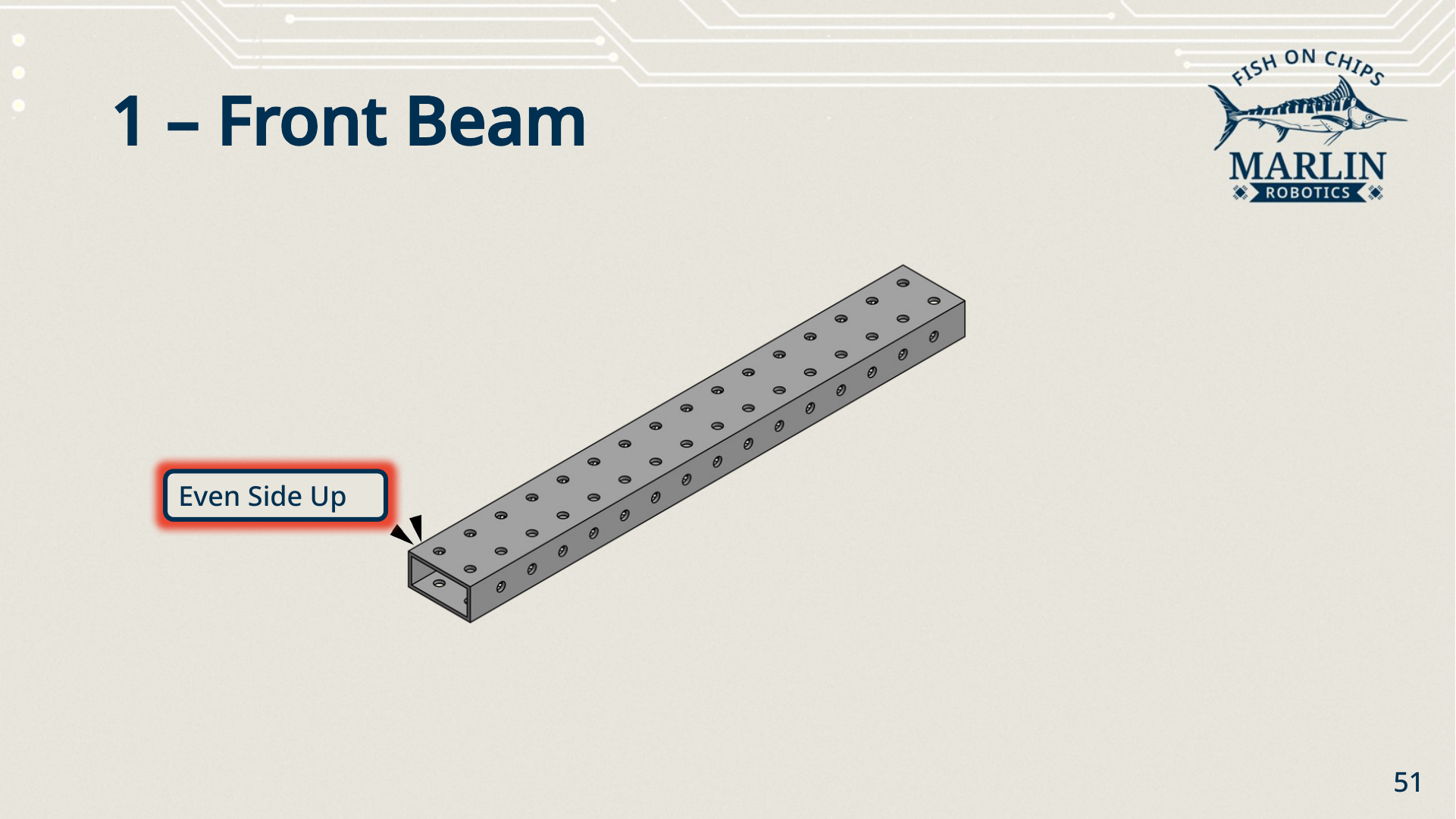
Lay one 2x full beam down across the front of the build, even side up. Everything else is positioned from this beam, so get its orientation right before you go on.
Centre beams
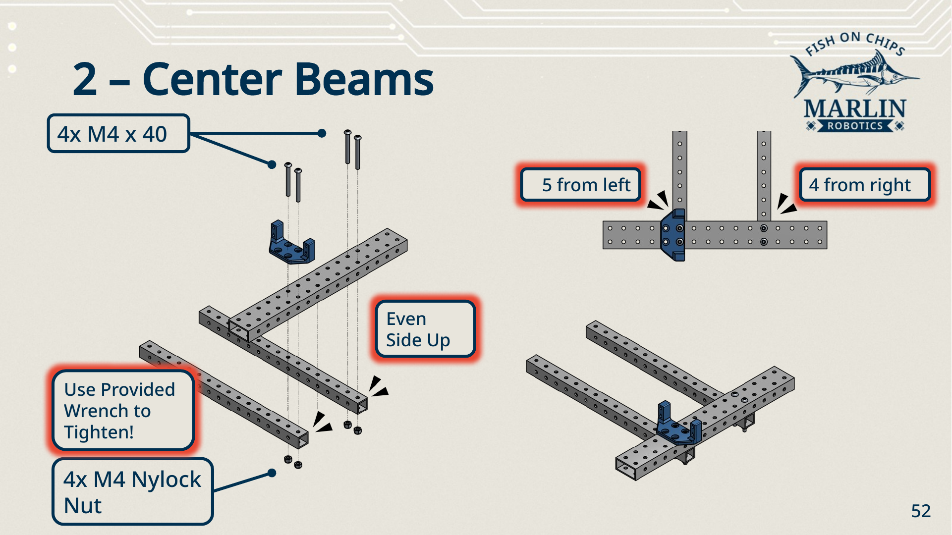
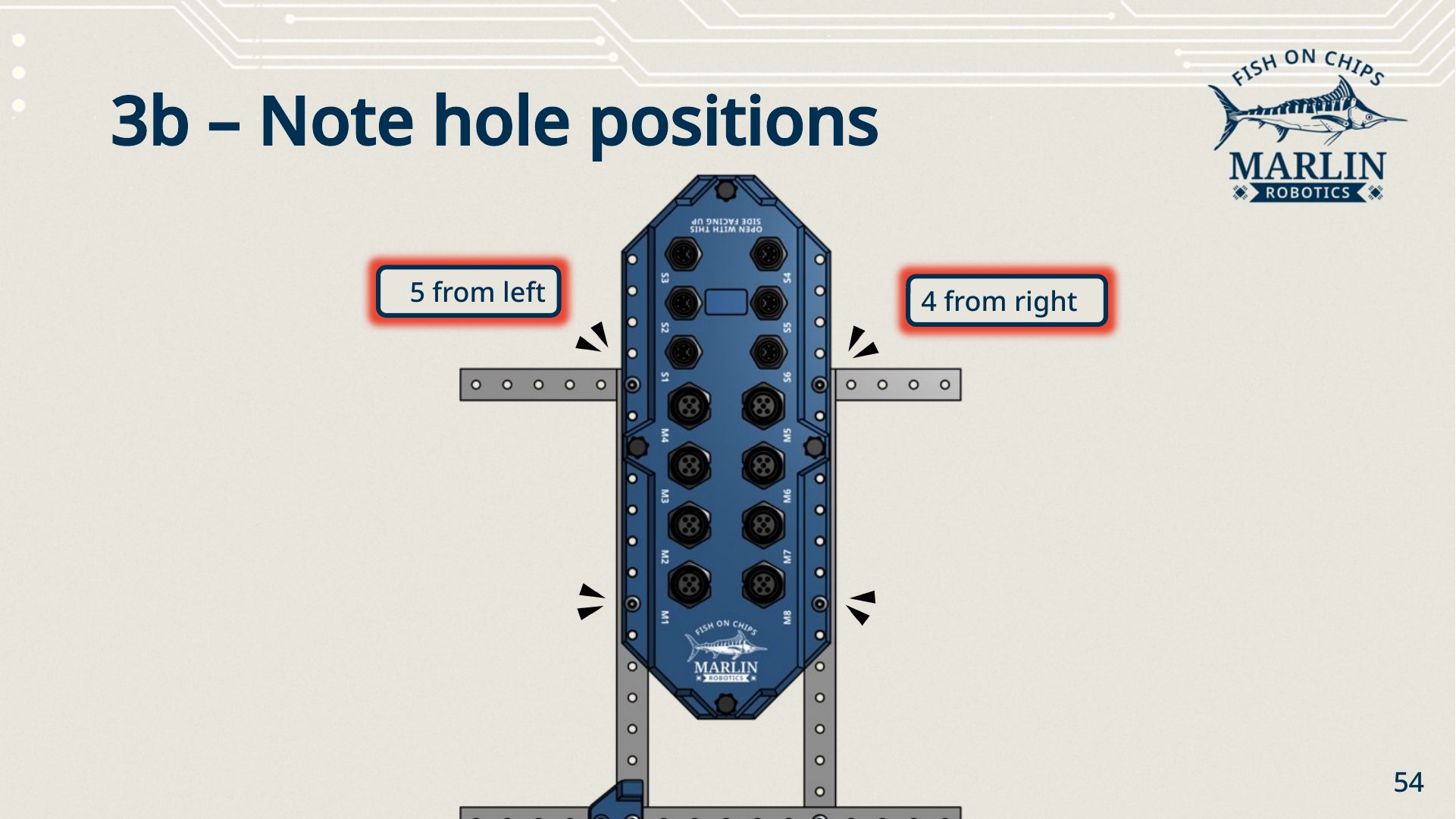
- Lay two 1x full beams across the front beam, running fore and aft, even side up. Position them at the 5th hole from the left and the 4th hole from the right.
- Sit the Servomotor Mount over the left-hand junction.
- Fix everything with 4× M4 × 40 and 4× M4 nylock nuts — two screws per junction. Tighten with the provided wrench.
Aft beam and Robot Brain
- Lay the last 1x full beam across the back of the two centre beams.
- Sit the Robot Brain on top, its mounting feet over the beam holes, with
the port labels (
M1–M8,S1–S6) readable from above. - Fix it with 2× M4 × 50 at the forward feet and 2× M4 × 30 at the aft feet, into 4× M4 nylock nuts underneath.
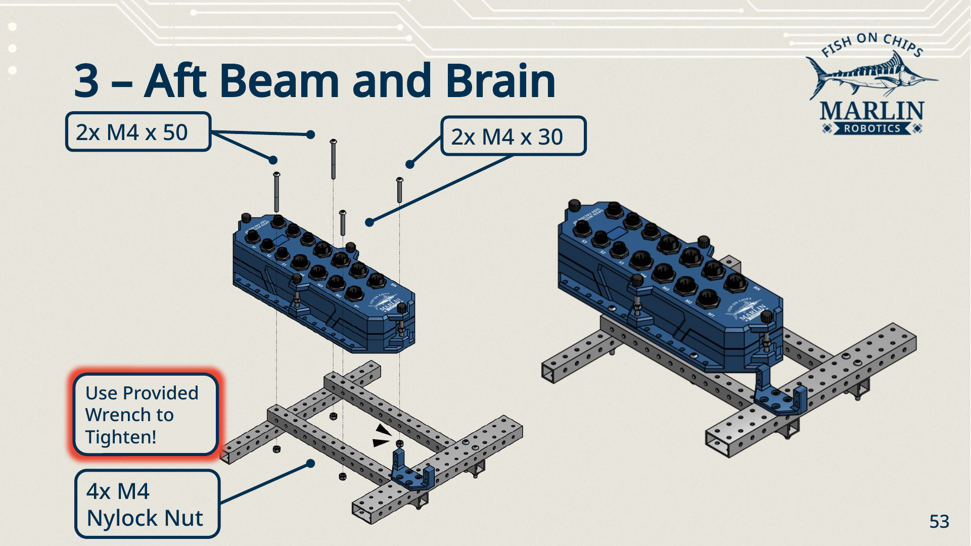
Check the hole positions from directly above before you tighten — the Brain should straddle the centre beams squarely, with the same 5 from the left, 4 from the right spacing as the beams themselves.
Left side
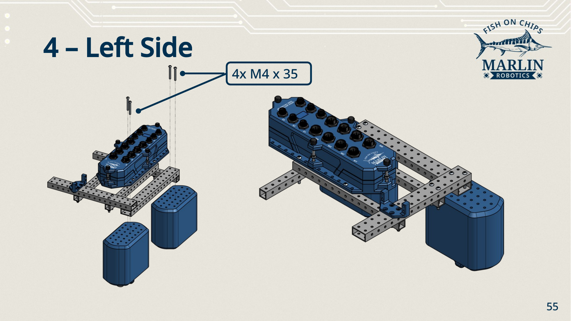
- Lay a 2x full beam along the left side, bridging the front and aft beams.
- Bring one plain Hull and one Thruster Hull up underneath it.
- Fix each Hull with 2× M4 × 35 down through the side beam — 4× M4 × 35 in total.
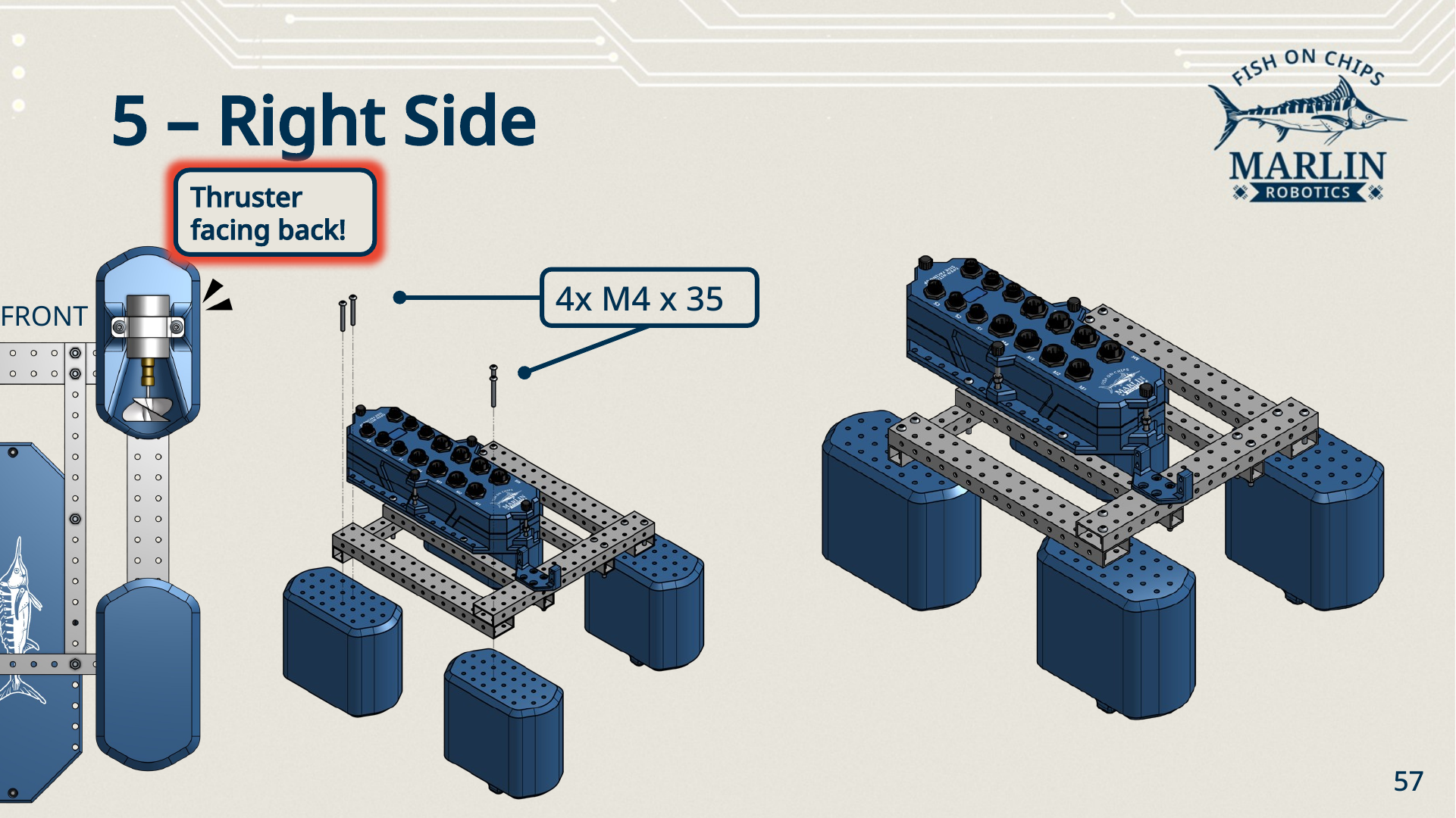
Thrusters face back, and the Hulls are offset
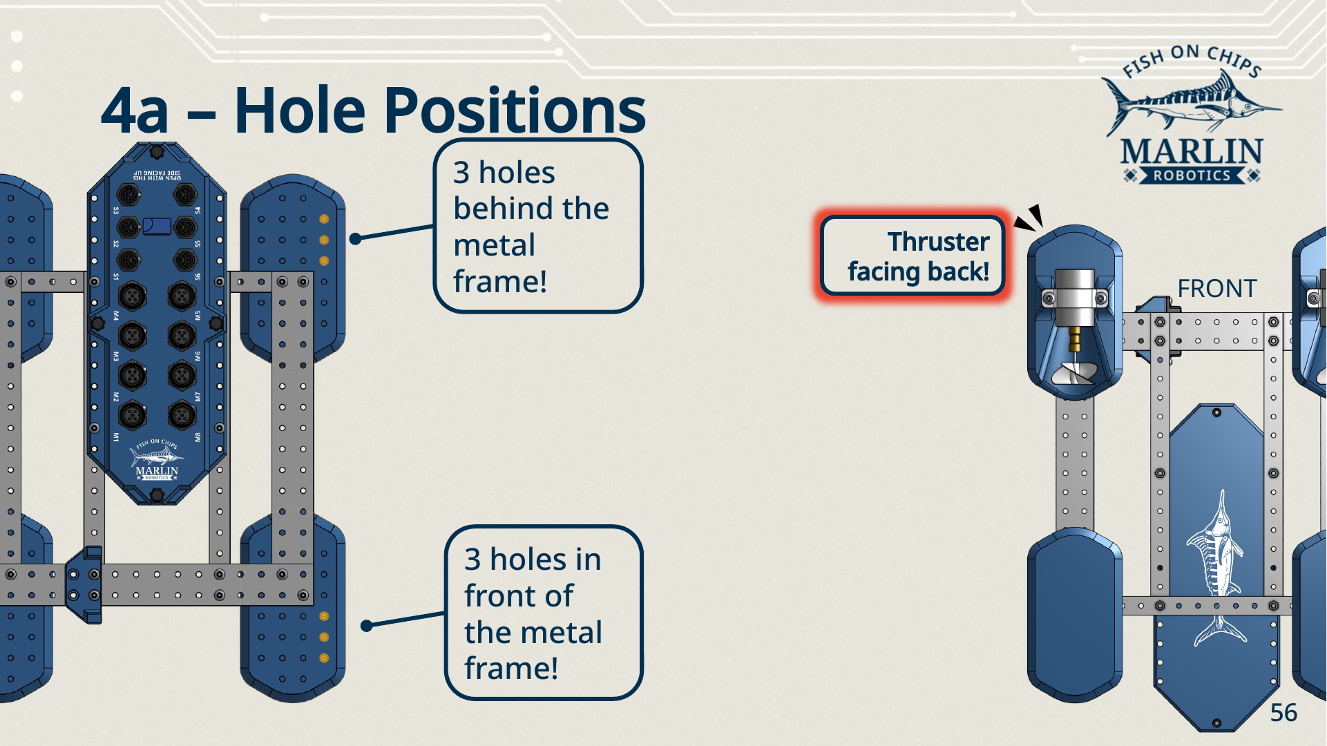
Both Thruster Hulls go at the front with their propellers facing aft — they push the Robot forwards. Set each Hull so there are 3 holes in front of the metal frame at the front position, and 3 holes behind the metal frame at the rear position. Getting this backwards leaves the Robot nose-heavy and driving in reverse.
Right side
Repeat step 4 on the right: one 2x full beam, one plain Hull, one Thruster Hull, 4× M4 × 35. Thruster facing back again, so the two propellers point the same way.
Keep the CW Thruster on one side and the CCW Thruster on the other.
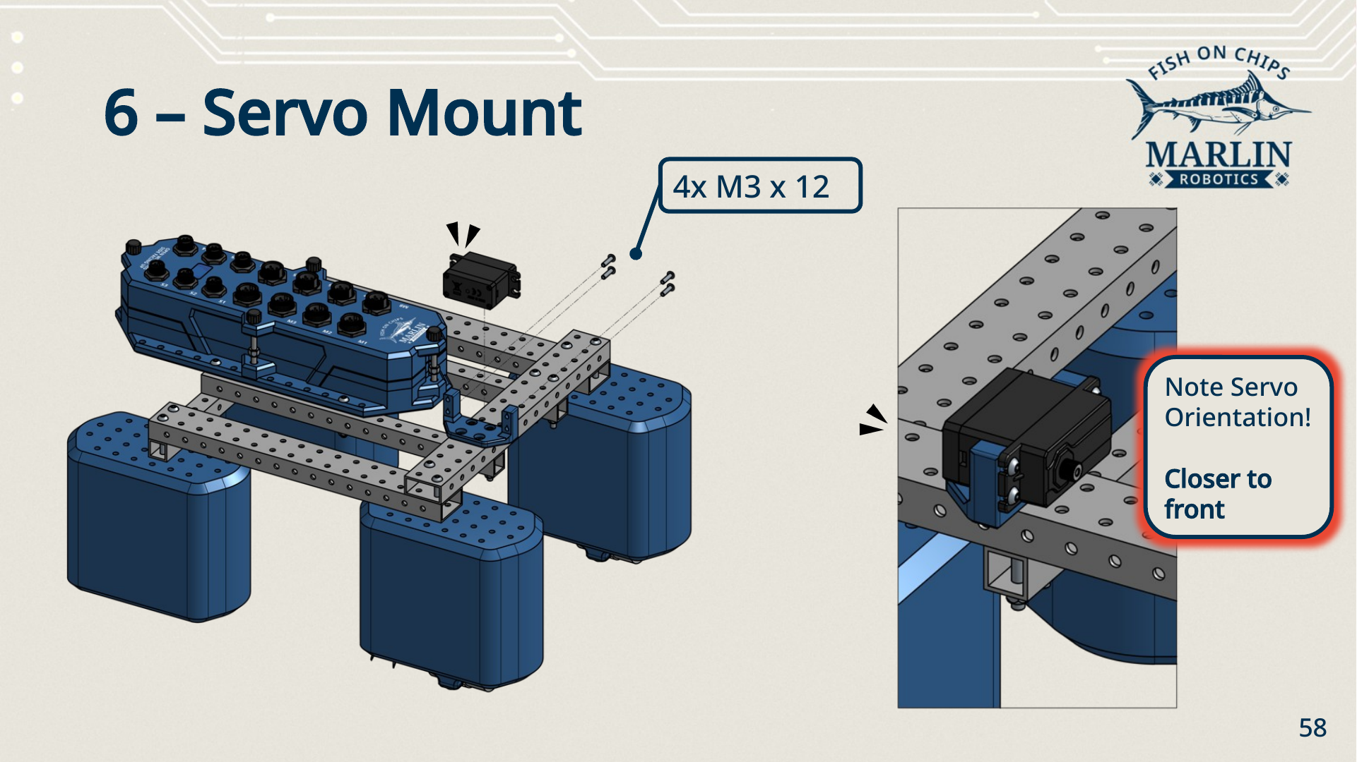
Servo
Bolt the Servo into the Servomotor Mount on the front beam with 4× M3 × 12.
Servo orientation
The Servo goes in with its output shaft closer to the front of the Robot, as shown in the detail view. The T Flipper's reach depends on it.
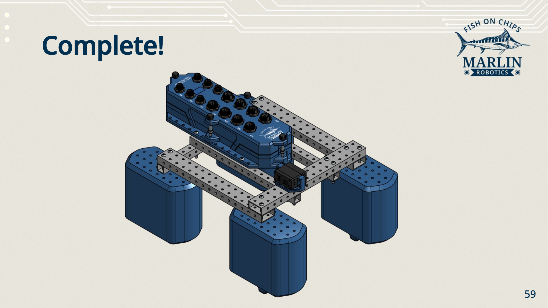
You should have: a frame standing on four Hulls, the Robot Brain bolted across the centre beams, and the Servo mounted on the front beam.
4. Sensors and cables
Parts
| Part | Quantity | From |
|---|---|---|
| IMU Sensor Module | 1 | — |
| LoRa Module | 1 | — |
| M4 × 30 screw | 4 | Fastener Box |
| M4 nylock nut | 4 | Fastener Box |
Telling the two modules apart
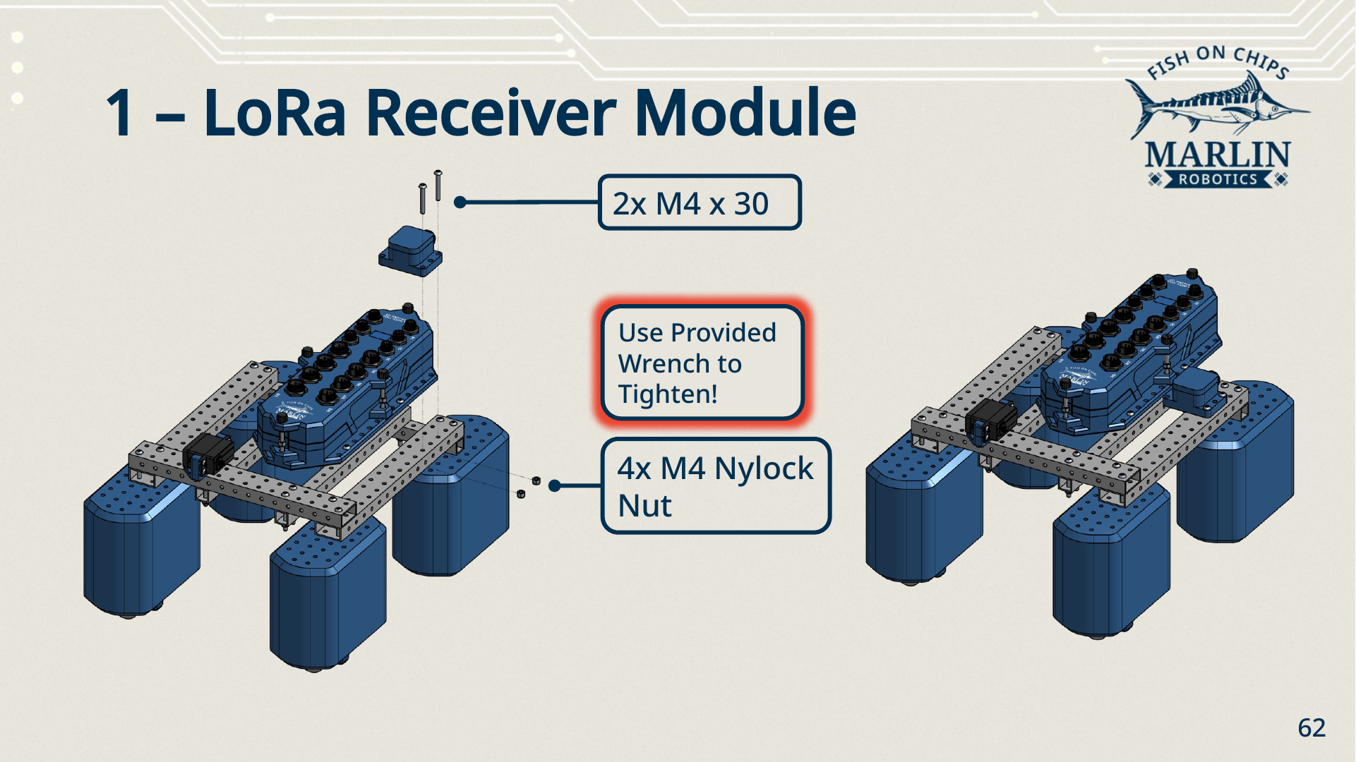
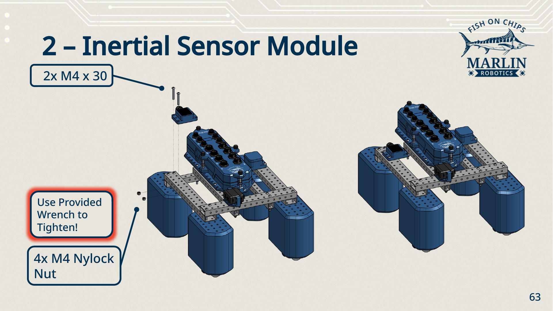
The IMU Sensor Module has a black top. The LoRa Module does not. They are the same size and take the same screws, so check the top before you bolt one down.
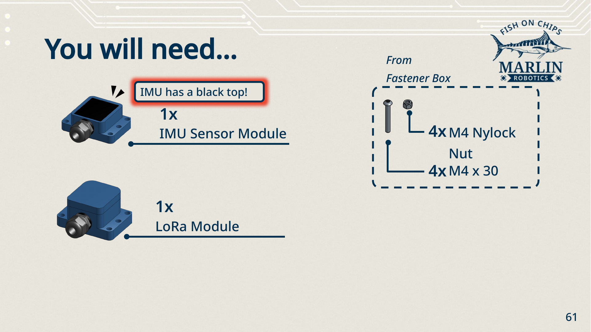
LoRa Module
Sit the LoRa Module on the frame beside the Robot Brain, cable gland pointing towards the Brain, and fix it with 2× M4 × 30 and 2× M4 nylock nuts. Tighten with the provided wrench.
IMU Sensor Module
Mount the IMU Sensor Module on the opposite side of the Robot Brain the same way: 2× M4 × 30 and 2× M4 nylock nuts.
Cables
Plug each device into the port your program will expect. The port names in your code have to match what you physically plugged in.
| Device | Port |
|---|---|
| IMU Sensor Module | S1 |
| LoRa Module | S6 |
| Servo | M2 |
| Right Thruster | M1 |
| Left Thruster | M8 |
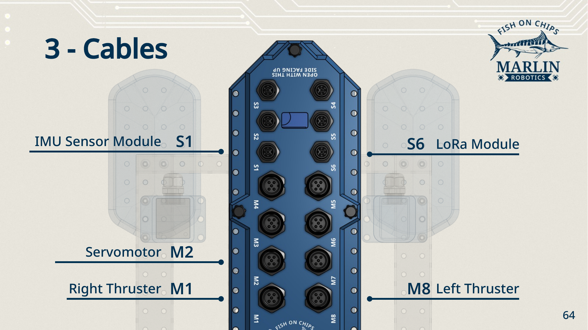
Screw each connector down finger-tight — they are sealed connectors, and a loose one lets water in.
5. Robot Brain battery
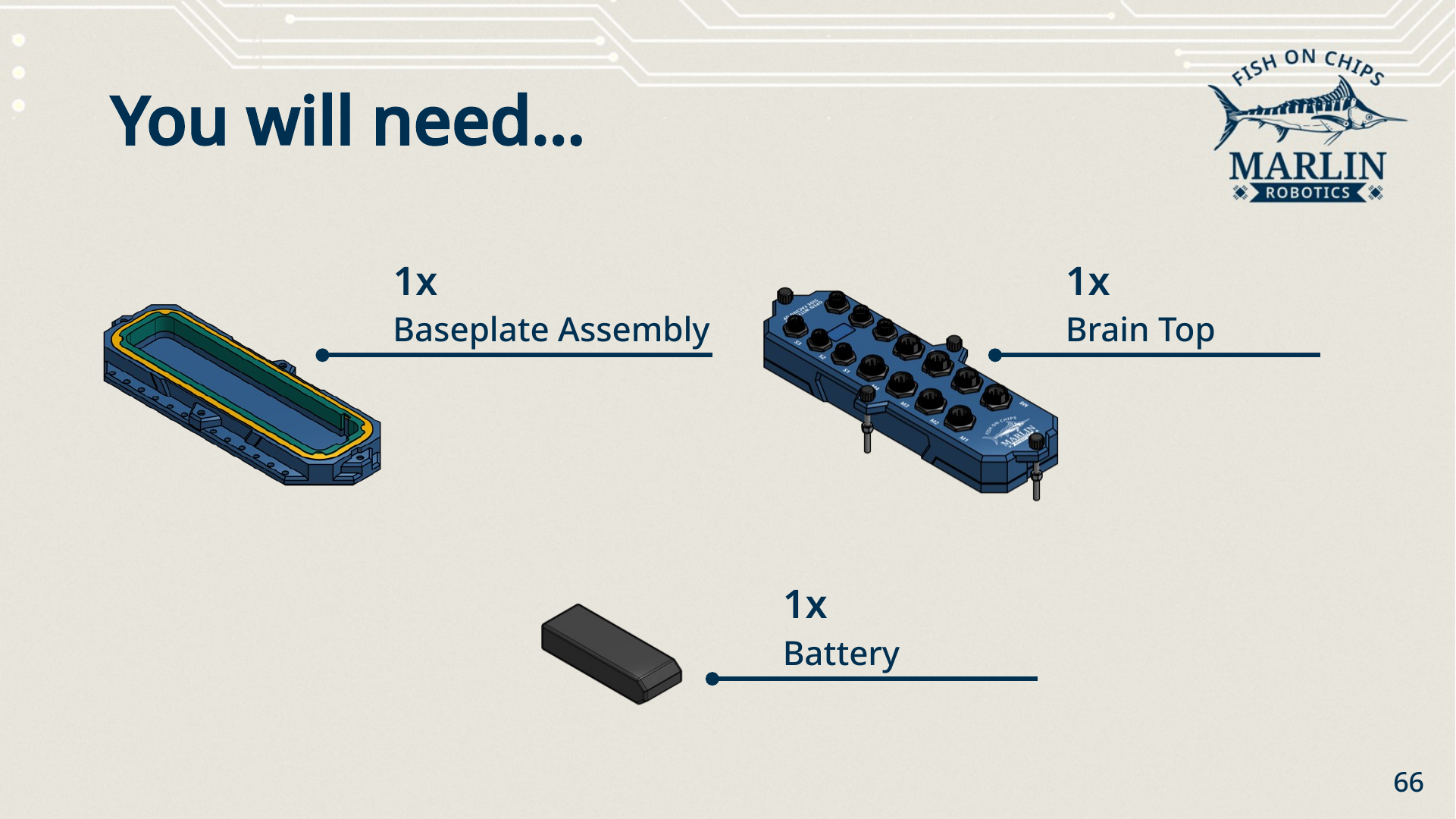
The Robot Brain ships sealed and empty. Open it once to fit the battery, then close it properly. Everything inside is electronics, and the seal is the only thing keeping the pool out.
Parts
| Part | Quantity |
|---|---|
| Baseplate assembly | 1 |
| Brain top | 1 |
| Battery | 1 |
Steps
-
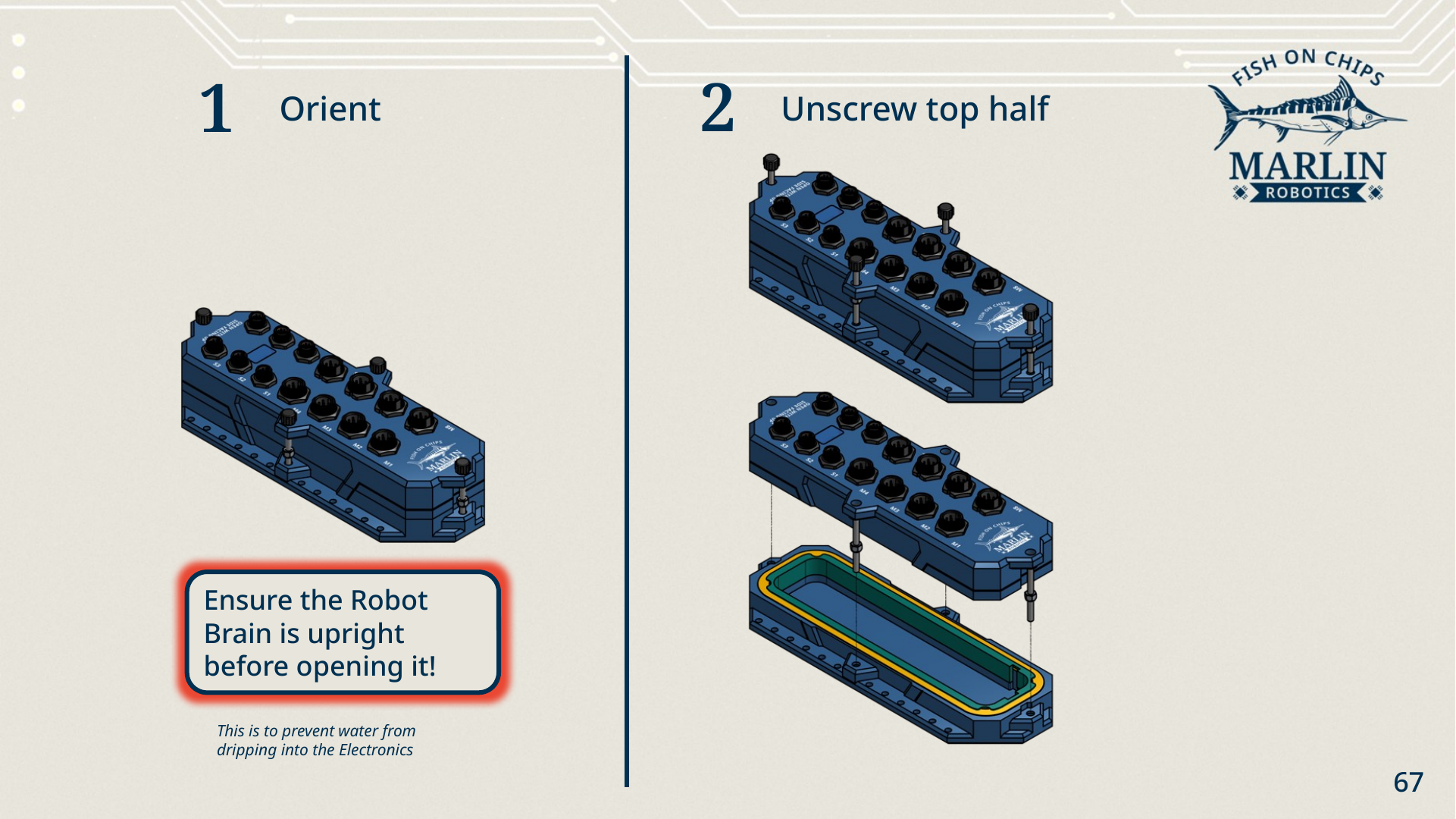
Orient. Set the Robot Brain upright on the bench.
Open it upright, never upside down
Any water sitting on the lid will run straight into the electronics if you open it inverted. Check it is the right way up before you loosen anything.
-
Unscrew the top half. Loosen the lid thumbscrews and lift the top off the baseplate. Use the Thumbscrew Wrench only for loosening — tightening with it over-torques the screws.
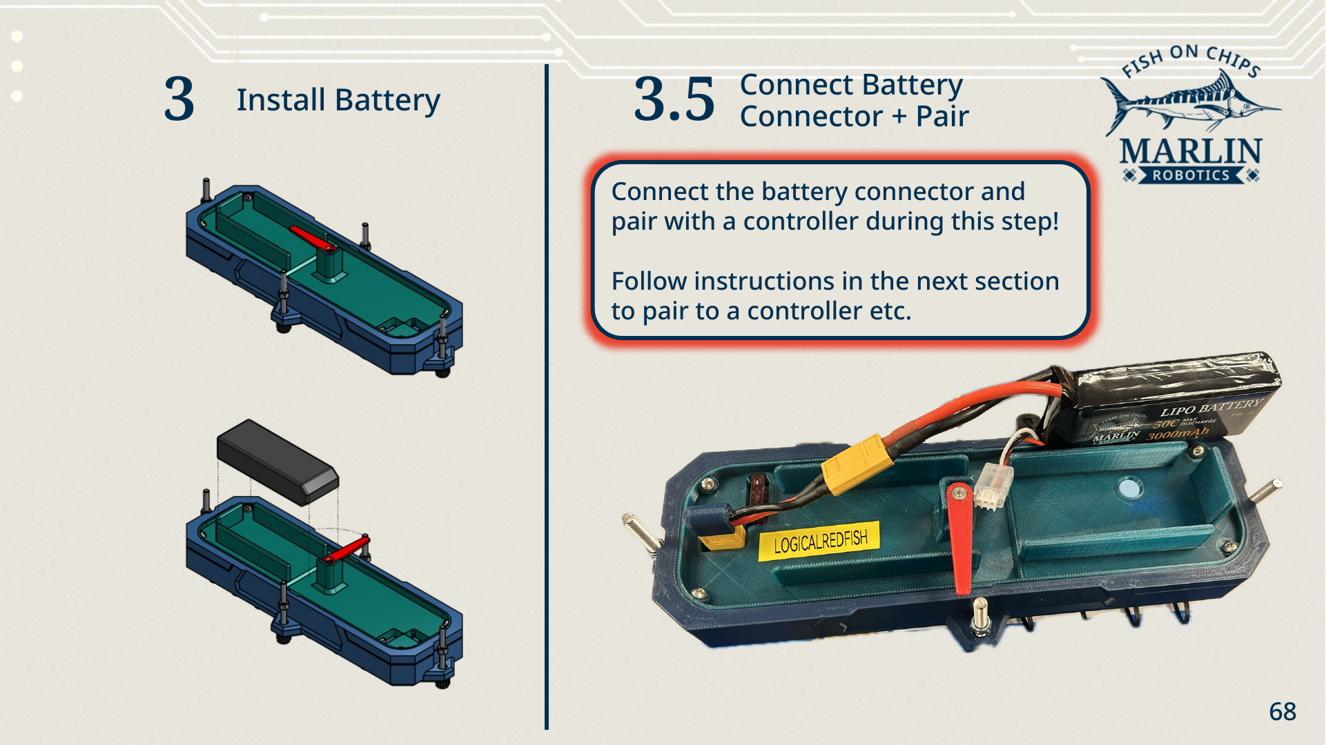
- Install the battery. Drop the battery into the tray.
-
Connect the battery connector. The Brain powers up as soon as it is connected.
Pair with a Controller while the box is open
This is the easiest moment to pair the Robot Brain with a Controller, because you can still reach everything inside. Follow Extension Walkthrough to connect a Controller and pair the Brain, then come back and close the box.
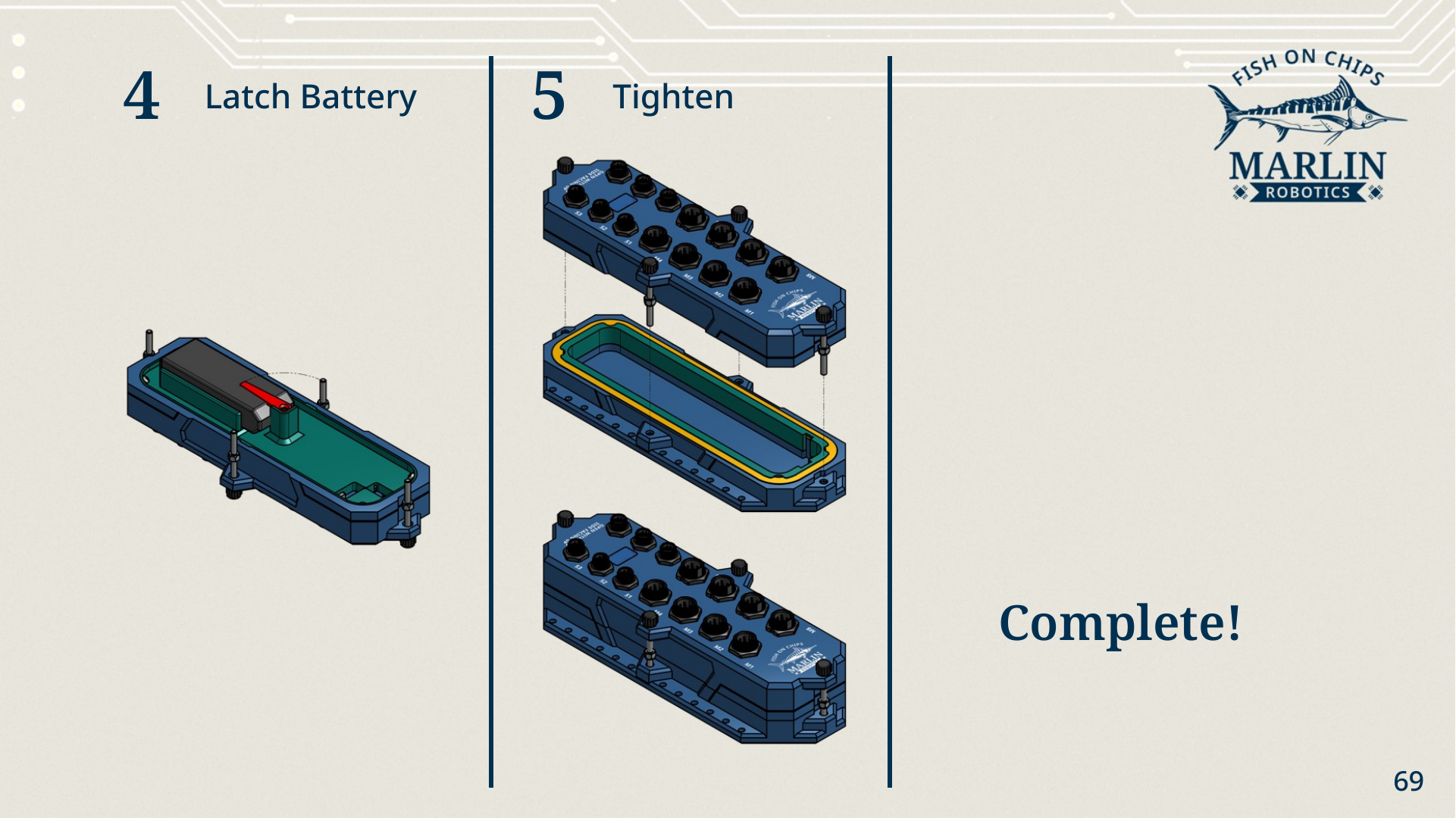
- Latch the battery. Swing the red latch over the battery so it cannot slide around.
-
Tighten. Refit the top over the gasket and tighten the thumbscrews evenly by hand.
Check the gasket before you tighten
The gasket must sit in its groove all the way round, with no cable pinched across it. A gasket that has popped out of the groove will not seal, and you will not find out until the Robot is in the water.
Before you move on
Your starter Robot is built. Ensure that the electronics are connected to the ports shown in the build guide. If you chose other ports, change the port numbers in the example code respectively.
You should have: a Robot standing on four Hulls, Thrusters facing aft, sensors and Servo wired to the Brain, a closed and sealed Robot Brain with its battery in — and the T Flipper set aside with its clamp screws still loose, waiting for the Servo to be zeroed.
Next: Set up MARLIN on your laptop in Installing MARLIN.